Major Richard Ira Bong, Air Corps, United States Army, Leyte, 12 December 1944. Major Bong is wearing the Medal of Honor. (U.S. Air Force)
17 December 1944: Major Richard Ira Bong, United States Army Air Corps, flying a Lockheed P-38 Lighting over San José on the Island of Mindoro, Commonwealth of the Philippines, shot down an enemy Nakajima Ki-43 Hayabusa (Allied reporting name, “Oscar”).
This was Bong’s 40th confirmed aerial victory and made him the leading American fighter ace of World War II. He is officially credited with 40 aircraft destroyed, 8 probably destroyed and 7 damaged.
Five days earlier, 12 December, during a ceremony at an American airfield on the Island of Leyte, Philippine Islands, General Douglas MacArthur, United States Army, had presented Major Bong the Medal of Honor.
An Associated Press reporter quoted the General:
“Of all military attributes, that one which arouses the greatest admiration is courage. It is the basis of all successful military ventures. our forces possess it to a high degree and various awards are provided to show the public’s appreciation. The Congress of the United States has reserved to itself the honor of decorating those amongst all who stand out as the bravest of the brave. It’s this high and noble category, Bong, that you now enter as I pin upon your tunic the Medal of Honor. Wear it as a symbol of the invincible courage you have displayed so often in mortal combat. My dear boy, may a merciful God continue to protect you is the constant prayer of your commander in chief.”
[On 18 December 1944, Douglas MacArthur was promoted to General of the Army, a five-star rank held by only nine other U.S. military officers. General MacArthur was the son of a Medal of Honor recipient, and had himself been twice nominated for the Medal for his actions during the occupation of Vera Cruz (1914) and the Meuse-Argonne Offensive (1918). He was awarded the Medal of Honor for his defense of the Philippines, 1941–42.]
General Douglas MacArthur talks with Major Richard I. Bong, Leyte, Philippine Islands, 12 December 1944. (U.S. Air Force)
Richard Bong’s citation reads:
MEDAL OF HONOR
The President of the United States of America, in the name of Congress, takes pleasure in presenting the Medal of Honor to Major (Air Corps) Richard Ira Bong, United States Army Air Forces, for conspicuous gallantry and intrepidity in action above and beyond the call of duty while serving with the 49th Fighter Group, V Fighter Command, Fifth Air Force, in action in the Southwest Pacific area from 10 October to 15 November 1944.
Though assigned to duty as gunnery instructor and neither required nor expected to perform combat duty, Major Bong voluntarily and at his own urgent request engaged in repeated combat missions, including unusually hazardous sorties over Balikpapan, Borneo, and in the Leyte area of the Philippines. His aggressiveness and daring resulted in his shooting down eight enemy airplanes during this period.
General Orders: War Department, General Orders No. 90, December 8, 1944 Action Date: October 10 – November 15, 1944 Service: Army Air Forces Rank: Major Regiment: 49th Fighter Group, V Fighter Command Division: 5th Air Force.
Dick Bong poses with “Marge,” his Lockheed P-38J-15-LO Lightning, 42-103993, Lockheed serial number 2827. A large photograph of his fiancée, Miss Marjorie Ann Vattendahl, is affixed to the fighter’s nose.
Major Bong flew a number of different Lockheed P-38s in combat. He is most associated, though, with P-38J-15-LO 42-103993, which he named Marge after his fiancée, Miss Marjorie Ann Vattendahl, a school teacher from Poplar, Wisconsin.
Richard Bong had flown 146 combat missions. General George C. Kenney, commanding the Far East Air Forces, relieved him from combat and ordered that he return to the United States. He was assigned to test new production P-80 Shooting Stars jet fighters being built at Lockheed Aircraft Corporation’s Burbank, California plant.
On 6 August 1945, the fuel pump of the new P-80 Bong was flying failed just after takeoff. The engine failed from fuel starvation and the airplane crashed into a residential area of North Hollywood, California. Major Richard Ira Bong was killed.
Nakajima Ki-43 Type 1 Army Fighter (AvionsLegendaires.net)
The Nakajima Ki-43 Type 1 Hayabusa was a single-place, single-engine fighter manufactured by Nakajima Hikoki K.K. for the Imperial Japanese Army Air Service. The light weight fighter was very maneuverable and was a deadly opponent. It was identified as “Oscar” by Allied forces. The Ki-43 shot down more Allied airplanes during World War II than any other Japanese fighter.
The Ki-43 was 29.2 feet (8.90 meters) long, with a wingspan of 35.6 feet (10.85 meters) and height of 9 feet (2.74 meters). Its empty weight was 4,170 pounds (1,878 kilograms) and gross weight was 5,500 pounds (2,495 kilograms).
The Ki-43 Type 1 Army Fighter was powered by an air-cooled, supercharged Nakajima Ha-115 Toku two-row, 14-cylinder radial engine which produced 925 horsepower at 9,350 feet (2,850 meters), 800 horsepower at 20,000 feet (6,096 meters), and 1,105 horsepower at Sea Level for takeoff. The engine drove a three-bladed constant-speed propeller with a diameter of 9.2 feet (2.80 meters).
Nakajima Ki-43 Type 1 Army Fighter, called “Oscar” by the Allied forces. (The Java Gold’s Blog)
Compared to American fighters, the Oscar was lightly armed with just two synchronized 7.7 mm × 58 mm Type 89 or 12.7 mm × 81 mm Type 1 machine guns, or a combination of one 7.7 mm and one 12.7 mm gun. The 12.7 machine gun could fire explosive ammunition. (The Type 89 was a licensed version of the Vickers .303-caliber machine gun, while the design of the Type 1 was based on the Browning M1921 .50-caliber machine gun.)
The Oscar’s maximum speed was 295 miles per hour (475 kilometers per hour) at Sea Level, and 347 miles per hour (558 kilometers per hour) at 20,000 feet (6,096 meters). Its service ceiling was 37,100 feet (11,308 meters). The maximum range with a normal fuel load of 149 U.S. gallons (564 liters) was 1,180 miles (1,899 kilometers) at 1,500 feet (457 meters).
Lockheed P-38J-10-LO Lightning 42-68008, Lockheed serial number 2519. (Lockheed Martin)
The Lockheed P-38 lightning is a single-place, mid-wing, twin-engine fighter. It is an unusual configuration, with the cockpit, weapons and nose landing gear in a central nacelle, and engines, turbochargers, cooling system and main landing gear in outer “booms.” The airplane was originally designed by Clarence L. “Kelly” Johnson.
The P-38J is 37 feet, 10 inches (11.532 meters) long, with a wingspan of 52 feet, 0 inches (15.850 meters) and overall height of 9 feet, 9-11/16 inches (2.989 meters). The fighter has an empty weight of 12,700 pounds (5,761 kilograms) and maximum gross weight of 21,600 pounds (9,798 kilograms).
The P-38J was powered by two liquid-cooled, turbosupercharged 1,710.597-cubic-inch displacement (28.032 liter) Allison Engineering Company V-1710-F-17R and -F17L (V-1710-89 and -91, respectively) single overhead cam (SOHC) 60° V-12 engines with a continuous power rating of 1,100 horsepower at 2,600 r,p.m., to 30,000 feet (9,144 meters), and a takeoff/military power rating of 1,425 horsepower at 3,000 r.p.m. The counter-rotating engines drove 11 feet, 6 inches (3.505 meters) diameter, three-bladed Curtiss Electric full-feathering constant-speed propellers through a 2.00:1 gear reduction. The engines were 7 feet, 1.34 inches (2.168 meters) long, 3 feet, 0.75 inches (0.933 meters) high, 2 feet, 5.28 inches (0.744 meters) wide, and weighed 1,350 pounds (612 kilograms).
A flight of two camouflaged Lockheed P-38J Lightnings, circa 1943. Dick Bong is flying the closer airplane, P-38J-5-LO 42-67183. (Lockheed Martin)
The P-38J had a maximum speed of 420 miles per hour (676 kilometers per hour) at 26,500 feet (8,077 meters). The service ceiling was 44,000 feet (13,411 meters). Carrying external fuel tanks, the Lightning had a maximum range of 2,260 miles (3,637 kilometers).
P-38s were armed with one 20 mm Hispano M2 aircraft autocannon with 150 rounds of ammunition, and four air-cooled Browning AN-M2 .50-caliber machine guns with 500 rounds per gun. All guns are grouped close together in the nose and aimed straight ahead.
A Lockheed P-38 Lighning test fires its guns. (Lockheed Martin)
Between 1939 and 1945, Lockheed Aircraft Corporation built 10,037 P-38 Lightnings at Burbank, California. 2,970 of these were P-38Js.
Major Richard Ira Bong, Air Corps, United States Army. (Richard I. Bong Veterans Historical Center/National Endowment for the Humanities)
Colonel Joseph Randall Holzapple, commanding officer, 319th Bombardment Group, Light, at Okinawa, 1945.
25–29 November 1945: Colonel Joseph Randall (“Randy”) Holzapple, U.S. Army Air Force, commanding officer of the 319th Bombardment Group, Light, departed Savannah, Georgia, as the pilot of a Douglas A-26C Invader twin-engine light attack bomber. His co-pilot on this flight was Lieutenant Colonel Charles R. Meyers. The navigator was Lieutenant Otto H. Schumaker and Corporal Howard J. Walden was the airplane’s radio operator.
The A-26 headed west, and kept heading west. 90 hours, 54 minutes later, Colonel Holzapple and his crew arrived at Washington National Airport, Washington, D.C. They had flown completely around the world, covering 24,859 miles (40,007 kilometers). The flight time was 96 hours, 50 minutes.
The A-26C Invader was built by Douglas Aircraft Company at its Long Beach, California and Tulsa, Oklahoma plants. It was 51 feet, 3 inches (15.621 meters) long with a wingspan of 70 feet, 0 inches (21.336 meters) and overall height of 18 feet, 6 inches (5.639 meters). It was designed to be flown by a single pilot, with a navigator/bombardier and a gunner. The A-26C weighed 22,690 pounds (10,292 kilograms) empty an had a maximum takeoff weight of 37,740 pounds (17,119 kilograms).
Power was supplied by two air-cooled, supercharged 2,804.4-cubic-inch-displacement (45.956 liter) Pratt & Whitney Double Wasp 2SB-G (R-2800-27) two-row, 18-cylinder radial engines with a compression ratio of 6.65:1. The R-2800-27 had a Normal Power rating of 1,600 horsepower at 2,400 r.p.m. at 5,700 feet (1,737 meters), 1,450 horsepower at 2,400 r.p.m. at 13,000 feet (3,962 meters), and 2,000 horsepower at 2,700 r.p.m for takeoff. War Emergency Power was 2,370 horsepower at 2,700 r.p.m. at Sea level. The engines turned three-bladed propellers with a diameter of 12 feet, 7 inches (3.835 meters) through a 2:1 gear reduction. The R-2800-27 was 6 feet, 3.72 inches (1.923 meters) long, 4 feet, 4.50 inches (1.334 meters) in diameter and weighed 2,300 pounds (1,043 kilograms).
The A-26 was a fast airplane for its time. It had a maximum speed of 323 knots (372 miles per hour/598 kilometers per hour) at 10,000 feet (3,048 meters). The service ceiling was 20,450 feet ( meters) and its range was 1,510 nautical miles (1,738 statute miles/2,797 kilometers) carrying a 4,000 pound (1,814 kilogram) bomb load.
Armament varied. The attack bomber could carry as much as 4,000 pounds (1,814 kilograms) of bombs in the bomb bay and 2,000 pounds (907 kilograms) on underwing hardpoints. Two Browning AN/M2 .50-caliber machine guns were mounted in upper and lower remotely-operated power turrets for defense, and as many as 14 forward-facing fixed .50-caliber machine guns were installed, with eight in the nose and three in each wing.
This Douglas A-26C-20-DT Invader, 43-22494, at the Pima Air And Space Museum, Tucson, Arizona, is marked as an aircraft of the 319th Bombardment Group, Light, at Okinawa, 1945. (Pima Air and Space Museum)Randall Holzapple (The 1932 Crest)
Joseph Randall Holzapple was born 7 September 1914 at Peoria, Illinois. He was the fourth of five children of Nathaniel A. Holzapple, a blacksmith, and Annetta Ritchie. He attended Pekin Junior High School, then Peoria High School, where he was a member of the French Club, Science and Math Club, and Drama Club. In his high school yearbook, Holzapple was called “refined” and “handsome.” He graduated in 1932.
In 1938, Randy Holzapple graduated from Bradley Polytechnic Institute, also in Peoria, with a bachelor of science degree in business administration. He then worked as an insurance salesman.
Joseph R. Holzapple enlisted as an aviation cadet in the Air Corps, United States Army, 31 December 1940. At the time, he was 5 feet, 8 inches (1.68 meters) tall and weighed 146 pounds (66 kilograms). He completed his flight training and on 16 August 1941, was commissioned a second lieutenant, Air Reserve.
On 25 March 1942, 2nd Lieutenant Bradley was appointed to the rank of 1st lieutenant, Army of the United States (Air Corps). Six months later, 11 September 1942, he was promoted to captain, A.U.S. (A.C.).
Captain Holzapple was assigned as operations officer of the 319th Bombardment Group (Medium), Eighth Air Force, in England. The group was equipped with the twin-engine Martin B-26 Marauder medium bomber. Operation Torch, the Allied invasion of North Africa, began on 8 November 1942, and the 319th deployed to Saint-Leu Airfield, northeast of Oran, Algeria, as an element of XII Bomber Command.
The wartime military often brought rapid advancement to qualified officers, and Holzapple was promoted to the rank of major, A.U.S. (A.C.), 5 February 1943. He took command of the 319th Group 13 August 1943, then in Tunisia. Major Holzapple was promoted to lieutenant colonel, A.U.S. (A.C.), on 13 September 1943. He was advanced to colonel, A.U.S. (A.C.), on 1 August 1944.
Lieutenant Colonel Joseph Randall Holzapple in the cockpit of a Martin B-26B-15-MA Marauder, 41-31753, circa 1943–44. (American Air Museum in Britain UPL 32425)
In November 1944, the 319th transitioned to the North American Aviation B-25 Mitchell medium bomber, but the group was returned to the continental United States in January 1945. It was then equipped with the Douglas A-26 Invader and redesignated the 319th Bombardment Group (Light).
On 1 March 1945, Colonel Holzapple married Miss Lois M. Miller in a ceremony at the Zion Evangelical Lutheran Church in Peoria. They would have two daughters, Nancy and Lynn.
The 319th redeployed to Okinawa in July 1945. It was was the first unit to be transferred from Europe to the Pacific as a complete unit.
This Douglas A-26C-30-DT Invader, 44-35281, was assigned to the 319th Bombardment Group at Naha, Okinawa, 1945. (U.S. Air Force)
Colonel Holzapple flew 91 combat missions in North Africa and the Mediterannean, and another 8 over Japan and China. For his service during World War II, he was awarded teh Silver Star, the Legion of Merit, the Distinguished Flying Cross with one oak leaf cluster (a second award), and the Air Medal with 17 oak leaf clusters (18 awards). He was also awarded the British Empire’s Distinguished Flying Cross and the Croix de Guerre by France.
Colonel Holzapple remained on active duty following the war. While he continued to hold his wartime rank, his permanent rank in the Air Corps, United States Army, was advanced to 1st lieutenant, on 5 July 1946, with date of rank from 7 September 1942.
Holzapple was assigned to a number of staff positions, before being sent to the Armed Forces Staff College, 1949–50. He was next assigned to the Armed Forces Special Weapons Project, the military agency responsible for maintenance, storage, security, handling and testing of nuclear weapons. In 1954, Colonel Holzaple was appointed assistant chief of staff for Operational Readiness at the Air Research and Development Command headquarters in Baltimore, Maryland. He also attended the National War College.
In 1955 Colonel Holzapple was assiged as commanding offier of the 47th Bombardment Wing, then based at RAF Sculthorpe, near Fakenham, Norfolk, England. The group was equipped with the North American Aviation B-45 Tornado four-engine jet bomber, and the Douglas B-26 Invader. ¹
From England, Holzapple went to Germany as deputy chief of staff for operations at Headquarters, United States Air Forces in Europe. Promoted to brigadier general, in 1958 he was appointed chief of staff, USAFE.
Brigadier General Holzapple returned to the weapons systems management with ARDC at Wright-Patterson Air Force Base.
From 1969–1971, General Holzapple served as Commander in Chief, United States Air Forces Europe, based at Wiesbaden, Germany.
General Holzapple retired from the U.S. Air Force 1 September 1971.
General Holzapple collapsed and died while playing squash at The Pentagon Athletic Center, Arlington, Virginia, 14 November 1973. He was 59 years old. He was buried at the Arlington National Cemetery.
General Joseph Randall Holzapple, United States Air Force.
¹ The Martin B-26 Marauder was withdrawn from service following World War II. Most of them were scrapped. In 1948, The Douglas A-26B and A-26C Invader light bombers were then designated B-26A and B-26B.
Ann Gilpin Baumgartner, circa 1944. (National Air and Space Museum)
14 October 1944: Ann Gilpin Baumgartner, a member of the Women Airforce Service Pilots (WASPs) assigned as Assistant Operations Officer of the Fighter Section, Flight Test Division, at Wright Field, Dayton, Ohio, made an evaluation flight of the Bell YP-59A Airacomet, becoming the first woman to fly a turbojet-propelled airplane.
The Airacomet was designed and built by the Bell Aircraft Corporation as an interceptor, powered by two turbojet engines. There were three XP-59A prototypes. The first one flew at Muroc Army Airfield on 1 October 1942. The Army Air Corps had ordered thirteen YP-59A service test aircraft. The first of these flew in August 1943 at Muroc.
The Bell YP-59A was conventional single place airplane with retractable tricycle landing gear. It was primarily of metal construction, though the control surfaces were fabric-covered. Its dimensions differed slightly from the XP-59A, having shorter wings with squared of tips, and a shorter, squared, vertical fin. There were various other minor changes, but the exact specifications of the YP-59As are uncertain.
Bell YP-59A-BE Airacomet 42-108775 at Wright Field. (U.S. Air Force)
The primary difference, though, was the change from the General Electric I-A turbojet to the I-16 (later designated J31-GE-1). Both were reverse-flown engines using a single-stage centrifugal compressor and a single-stage turbine. The I-16 produced 1,610 pounds of thrust (7.16 kilonewtons). They were 6 feet, 0 inches long, 3 feet, 5.5 inches in diameter and weigh 865 pounds (392 kilograms),
Even with the two I-16s producing 720 pounds of thrust (3.20 kilonewtons) more than the the XP-59A’s I-A engines, the YP-59A’s performance did not improve. Engineers had a lot to learn about turbojeft engine inlet design.
The YP-59A had a maximum speed of 409 miles per hour (658 kilometers per hour) at 35,000 feet (10,668 meters), and its service ceiling was 43,200 feet (13,167 meters).
Bell YP-59A-BE Airacomet 42-108775 at Wright Field. (U.S. Air Force)
The P-59 was ordered into production and Bell Aircraft Corporation built thirty P-59A and twenty P-59B fighters. These were armed with one M4 37mm autocannon with 44 rounds of ammunition and three Browning AN-M2 .50-caliber machine guns with 200 rounds per gun.
Although a YP-59A had set an unofficial altitude record of 47,600 feet (14,508 meters), the Airacomet was so outclassed by standard production fighters that no more were ordered.
Bell YP-59A-BE Airacomet 42-108775 at Wright Field. (U.S. Air Force)Ann G. Baumgartner stands on the wing of a North American Aviation T-6 Texan. (U.S. Air Force)
Ann Gilpin Baumgartner was born 27 Aug 1918, at the U.S. Army Hospital, Fort Gordon, Augusta, Georgia. She was the daughter of Edgar F. Baumgartner, engineer and patent attorney, and Margaret L. Gilpin-Brown Baumgartner. After graduating from Walnut Hill High School, Natick, Massachussetts, she studied pre-med at Smith College, Northampton, Massachussetts. She played soccer and was on the swimming team. She graduated in 1939.
Miss Baumgartner worked as a reporter for The New York Times. She took flying lessons at Somerset Hills Airport, Basking Ridge, New Jersey, and soloed after only eight hours. She then bought Piper Cub to gain flight experience.
Ann G. Baumgartner, WASP Class 43-W-3. (U.S. Air Force)
After being interviewed by Jackie Cochran, Baumgartner joined the Women Airforce Service Pilots (WASPs) 23 March 1943, a member of Class 43-W-3, graduating 11 September 1943 with Class 43-W-5. She was then assigned to Camp Davis Army Airfield, Holly Ridge, North Carolina, where she towed targets for anti-aircraft artillery training.
Miss Baumgartner was transferred to Wright Field, Dayton, Ohio (now, Wright-Patterson Air Force Base), where she flew the B-24 Liberator and B-29 Superfortress heavy bombers, P-38 Lightning, P-47 Thunderbolt, YP-59A Airacomet, P-82 Twin Mustang fighters, and the Luftwaffe Junkers Ju 88 medium bomber.
While at Wright Field, Miss Baumgartner met Major William Price Carl, who was an engineer associated with the P-82. They were married 2 May 1945, and would have two children.
Miss Baumgartner was released from service 20 December 1944, when the WASPs were disbanded. Following World War II, she was employed as an instrument flight instructor for United Air Lines.
After they retired, Mr. and Mrs. Carl sailed the Atlantic Ocean aboard their sailboat, Audacious.
Mrs. Carl was the author of A WASP Among Eagles and The Small World of Long-Distance Sailors.
Ann Gilpin Baumgartner Carl died at Kilmarnock, Virginia, 20 March 2008, at the age of 89 years. She and her husband, who had died one month earlier, were buried at sea.
The Curtiss-Wright XP-40 prototype, 38-10, on its first flight, 14 October 1938. Test pilot Ed Elliot is in the cockpit. (San Diego Air and Space Museum Archives) 16_008532
14 October 1938: At Buffalo, New York, test pilot Everett Edward Elliot made the first flight in the new Curtiss-Wright Corporation’s Model 75P, a prototype for a single-engine pursuit plane which had been designated XP-40 by the U.S. Army Air Corps.
Curtiss-Wright’s Chief Engineer, Donovan Reese Berlin, had taken the tenth production P-36A Hawk, Air Corps serial number 38-10, and had its air-cooled radial engine replaced with the Harold Caminez-designed, liquid-cooled, supercharged, 1,710.597-cubic-inch-displacement (28.032 liter) Allison Engineering Co. V-1710-C13 (V-1710-19).
Donovan Reese Berlin. (Niagara Aerospace Museum)
The V-1710-19 was a single overhead cam (SOHC) 60° V-12 engine with four valves per cylinder and a compression ration of 6.65:1. It had a Normal Power rating of 910 horsepower at 2,600 r.p.m. at Sea Level, and 1,060 horsepower at 2,950 r.p.m. for Takeoff. At 10,000 feet (3,048 meters), the V-1710-19 had Maximum Continuous Power rating of 1,000 horsepower at 2,600 r.p.m., and Military Power rating of 1,150 horsepower at 2,950 r.p.m. The engine required 100/130-octane aviation gasoline. It drove a three-bladed Curtiss Electric constant-speed propeller through a 2:1 gear reduction. The V-1710-19 was 8 feet, 1.75 inches (2.483 meters) long, 3 feet, 4.75 inches (1.035 meters) high and 2 feet, 4.94 inches (0.735 meters) wide. It weighed 1,320 pounds (599 kilograms).
Curtiss-Wright XP-40 38-10 (SDASM 16_008531)
At 1,829.39-cubic-inches (29.978 liters), the original Pratt & Whitney Twin Wasp S1C1-G (R-1830-17) 14-cylinder radial engine had greater displacement and produced 80 horsepower more for takeoff than the Allison V-12. The long, narrow V-12, though, allowed for a much more streamlined engine cowling for higher speed and greater efficiency.
XP-40 16_008533Curtiss-Wright XP-40 prototype. (SDASM 16_008534)The Curtiss-Wright XP-40 in the original configuration at Langley Field. (NASA)Everett Edward Elliot (1907–1981).
In the early testing, the XP-40 was much slower than expected, reaching only 315 miles per hour (507 kilometers per hour). (The P-36A Hawk had a maximum speed of 313 miles per hour). Engineers experimented with different placement for the coolant radiator, oil coolers and the engine air intake. The Air Corps project officer, Lieutenant Benjamin Scovill Kelsey, had the prototype sent to the National Advisory Committee for Aeronautics (NACA) Research Center at Langley Field, Virginia, where the full-size airplane was placed inside a wind tunnel.
Over a two-month period, NACA engineers made a number of improvements. The radiator was moved forward under the engine and the oil coolers utilized the same air scoop. The exhaust manifolds were improved as were the landing gear doors.
When they had finished, Lieutenant Kelsey flew the modified XP-40 back to Curtiss. Its speed had been increased to 354 miles per hour (570 kilometers per hour), a 12% improvement.
By December 1939 the airplane had been further improved and was capable of 366 miles per hour (589 kilometers per hour).
The Curtiss-Wright XP-40 prototype in a wind tunnel at Langley Field, 24 April 1939. (NASA)Curtiss-Wright XP-40 in the NACA Full Scale Wind Tunnel at Langley Field, Virginia, 24 April 1939. (NASA)
The Curtiss Hawk 75P, XP-40 38-10, was 31 feet, 1 inch (9.574 meters) long with a wingspan of 37 feet, 4 inches (11.354 meters) and overall height of 12 feet, 4 inches (3.734 meters). It had an empty weight of 5,417 pounds (2,457.1 kilograms) and maximum gross weight of 6,870 pounds (3,116.2 kilograms).
The prototype had a maximum speed of 342 miles per hour (550 kilometers per hour) at 12,200 feet (3,719 meters) with a gross weight of 6,260 pounds (2,839.5 kilograms). Its range was 460 miles (740 kilometers) flying at 299 miles per hour (481 kilometers per hour) with 100 gallons (378.5 liters) of fuel. With 159 gallons (601.9 liters) and with speed reduced to 200 miles per hour (322 kilometers per hour), the XP-40 had a maximum range of 1,180 miles (1,899 kilometers).
The prototype was armed with two air-cooled Browning AN-M2 .50-caliber machine guns mounted above the engine and synchronized to fire forward through the propeller arc.
The Air Corps placed an initial order for 524 P-40s. This was the largest single order for airplanes by the U.S. military up to that time. The first production model was the P-40 Warhawk, armed with two .50-caliber machine guns. There was only one P-40A variant which was a P-40 modified as a camera aircraft. The definitive pursuit model was the P-40B Warhawk, which retained the two .50-caliber guns of the P-40 and added two Browning M2 .30-caliber machine guns to each of the wings.
A Curtiss-Wright P-40B Warhawk, 79th Pursuit Squadron, 20th Pursuit Group, Hamilton Field, California, 1940. (U.S. Air Force)
The P-40B was best known as the airplane flown by the American Volunteer Group fighting for China against the Japanese. They were called the “Flying Tigers”. Between 1939 and 1945, Curtiss built 13,738 P-40s in many configurations. They flew in combat in every theater of operations during World War II.
A Curtiss-Wright Hawk 81-A3 (Tomahawk IIb) of the American Volunteer Group, Kunming, China, 1942. (U.S. Air Force)
Lt. (j.g.) George H.W. Bush, USNR, VT-51, in cockpit of General Motors TBM-1C Avenger Bu.No. 46214, USS San Jacinto (CVL-30), 1944. (U.S.Navy)
2 September 1944: Lieutenant (Junior Grade) George Herbert Walker Bush, United States Naval Reserve, led a flight of four TBF/TBM Avenger torpedo bombers of Torpedo Squadron 51 (VT-51), from the Independence-class light aircraft carrier USS San Jacinto (CVL-30), against a radio transmission station on the island of Chichi-Jima.
The Avenger had a crew of three. Along with Lt (j.g.) Bush were Lt. (j.g.) William G. White, USNR, gunner, and radio operator ARM 2/c John Lawson Delaney, USNR.
Undated photo of future United States President George H.W. Bush as a United States Navy pilot seated in the cockpit of an Avenger. (U.S. Navy)
Each airplane was armed with four 500-pound¹ general purpose bombs. The flight was joined by eight Curtiss-Wright SB2C Helldiver dive bombers of VB-20, escorted by twelve Grumman F6F-5 Hellcat fighters of VF-20, from USS Enterprise (CV-6).
Chichi-Jima is the largest island in the Ogasawara Archipelago of the Bonin Islands, approximately 150 miles (240 kilometers) north of Iwo Jima and 620 miles (1,000 kilometers) south of Tokyo, Japan. The United States Hydrographic Survey described the island in 1920 as “very irregular in shape,” approximately 4¼ miles (7.2 kilometers) long and 2 miles (3.2 kilometers) wide. The area of the island is presently given as 23.45 square kilometers (9.05 square miles). Its highest point is 326 meters (1,070 feet) above Sea level. The island has a small sea port where midget submarines were based beginning in August 1944. Chichi-Jima was heavily garrisoned with 20,656 Imperial Japanese Army and Navy personnel, and 2,285 civilian workers.²
A Curtiss-Wright SB2C Helldiver over Chichi Jima. (U.S. Navy)
Lieutenant Bush’s flight was scheduled for a time over target of 0825–0830. They encountered heavy antiaircraft fire and Bush’s Avenger was hit. With the torpedo bomber on fire, Bush continued the attack and later reported good results. Unable to return to the aircraft carrier, he flew away from the island to limit the risk of capture of the crew by the enemy when they bailed out.
Bush and one other crewman (which one is not known) bailed out. While Bush parachuted safely, the second crewman’s parachute never opened. The third crewman went down with the airplane. Both Lieutenant White and Radioman Delaney were killed.
The Gato-class fleet submarine USS Finback (SS-230) was stationed near the island on lifeguard duty during the attack. At 0933, Finback was notified of an aircraft down nine miles northeast of Minami-Jima. Escorted by two F6F fighters, the submarine headed for the location. At 1156, Finback picked up Lt. Bush, floating in his life raft. A search for White and Delaney was unsuccessful. Their bodies were not recovered.
Lt. (j.g.) George H. W. Bush, USNR, in inflatable raft, is rescued by the crew of USS Finback (SS-230), 2 September 1944. (U.S. Navy)
(Later that same day, Finback, while submerged, towed a second pilot and his life raft away from Magane-Iwa, as he held on to the sub’s periscope.)
Lieutenant Bush and the other rescued pilots remained aboard for the remainder of Finback‘s war patrol (her tenth), and were then returned to Pearl Harbor. In November he rejoined San Jacinto for operations in the Philippines.
Gato-class fleet submarine USS Finback (SS-230) off New London, Connecticut, 7 March 1949. (U.S. Navy)
George Herbert Walker Bush was born at Milton, Massachusetts, 12 June 1924, the son of Prescott Sheldon Bush and Dorothy Walker Bush. He attended high school at the Phillips Academy in Andover, Massachusetts.
One day after his 18th birthday, 13 June 1942, Bush enlisted as a seaman, 2nd class, in the United States Naval Reserve. He was appointed an aviation cadet and underwent preflight training at the University of North Carolina, Chapel Hill. He was honorably discharged 8 June, and commissioned as an ensign, United States Naval Reserve, 9 June 1943. At the age of 19 years, 2 days, he became the youngest Naval Aviator in history. (His age record was broken the following month by Ensign Charles Stanley Downey, who was commissioned 16 July 1943 at the age of 18 years, 11 months, 14 days.)
Aviation Cadet George H. W. Bush, USNR, 1942. (U.S. Navy)
Ensign Bush continued flight training at NAS Pensacola, Florida, and then the Carrier Qualification Training Unit, NAS Glenville, Illinois. After training with the Atlantic Fleet, Ensign Bush was assigned to Torpedo Squadron Fifty-One (VT-51), in September 1943. He was promoted to lieutenant (junior grade), 1 August 1944.
After leaving San Jacinto, Bush was assigned to NAS Norfolk, Virginia, from December 1944 to February 1945. He then joined Torpedo Squadron Ninety-Seven (VT-97) and then VT-153.
Lieutenant (j.g.) Bush was released from active duty on 18 September 1945, retaining his commission. He was promoted to lieutenant 16 November 1948. On 24 October 1955, Lieutenant Bush resigned from the U.S. Navy.
During World War II, George H. W. Bush flew 58 combat missions. He flew a total of 1,221 hours and made 126 carrier landings. He was awarded the Distinguished Flying Cross, the Air Medal with two gold stars (three awards), and the Presidential Unit Citation.
He would later become the forty-first President of the United States of America.
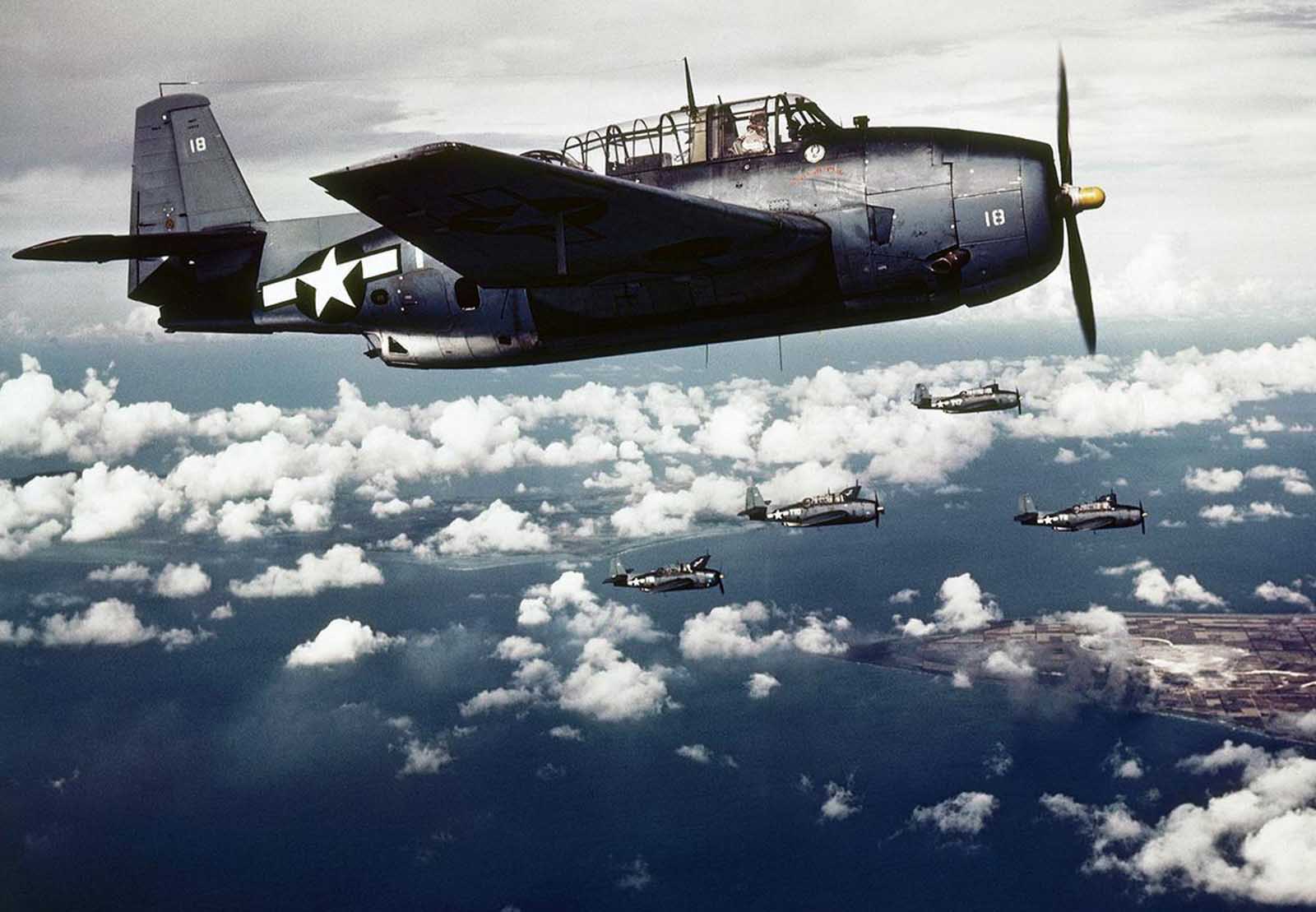
Grumman TBF or General Motors TBM Avengers over Wake Island, 1943. (U.S. Navy)
The airplane flown by Lt. (j.g.) Bush on 2 September 1944 was a General Motors TBM-1C Avenger torpedo bomber, Bu. No. 46214. This was a licensed variant of the Grumman TBF-1C Avenger, built by the General Motors Corporation Eastern Aircraft Division at Linden, New Jersey.
The Avenger was designed by Robert Leicester Hall, Chief Engineer and Test Pilot for the Grumman Aircraft Engineering Corporation, Bethpage, New York. The prototype XTBF-1 made its first flight 1 August 1941. It was a large single-engine aircraft, operated by a crew of three (pilot, radio operator and ball turret gunner). It was equipped with folding wings for storage on aircraft carriers. Production of the torpedo bomber began with the opening of a new manufacturing plant, Sunday, 7 December 1941. The first production Avenger was delivered to the U.S. Navy in January 1942.
The TBF-1 and TBM-1 were 40 feet, 11 inches (12.471 meters) long, with a wingspan of 54 feet, 2 inches (16.510 meters) and overall height of 16 feet, 5 inches (5.004 meters). The airplane had an empty weight of 10,545 pounds (478 kilograms), and its maximum gross eight was 17,895 pounds (8,117 kilograms). The Avenger was the largest single-engine aircraft of World War II.
LCDR Albert B. Cahn, USN, gives the take-of signal to a General Motors TBM-1C Avenger of Torpedo Squadron 51 (VT-51) aboard the light aircraft carrier USS San Jacinto (CVL-30), during exercises on 16 May 1944. (U.S. Navy)
The Avenger was powered by one of several variants of the Wright Aeronautical Division Cyclone 14 (R-2600): GR2600B698 (R-2600-8 and -8A); GR2600B676 (R-2600-10); and 776C14B31. The R-2600 was series of air-cooled, supercharged, 2,603.737-cubic-inch-displacement (42.688 liter), two-row 14-cylinder radial engines. The engines used in the Avengers all had a compression ratio of 6.9:1, supercharger ratios of 7.06:1 and 10.06:1, and propeller gear reduction ratio of 0.5625:1.
The R-2600-8, -8A and -10 had Normal Power ratings of 1,500 horsepower at 2,400 r.p.m. at Sea Level, and 1,700 horsepower at 2,600 r.p.m. for takeoff. The R-2600-20 was rated at 1,600 horsepower at 2,400 r.p.m., and 1,900 horsepower at 2,800 horsepower, respectively.
Dimensions and weights varied. The R-2600-8 and -8A were 64.91 inches (1.649 meters) long. The -10 was 74.91 inches (1.903 meters) long, and the length of the -20 was 66.08 inches (1.678 meter). The R-2600-8 and 8A and -10 were 54.26 inches (1.378 meters) in diameter. The -20 was 54.08 inches (1.374 meters). The -8 and -8A both weighed 1,995 pounds (905 kilograms). The -10 weighed 2,115 pounds (959 kilograms) and the -20 weighed 2,045 pounds (928 kilograms).
The engines drove a three-bladed Hamilton Standard Hydromatic constant-speed propeller.
The TBF/TBM had a cruise speed of 147 miles per hour (237 kilometers per hour) and maximum speed of 276 miles per hour (444 kilometers per hour) at 16,500 feet (5,029 meters). The service ceiling was 30,100 feet (9,174 meters). Its maximum range was 1,010 miles (1,625 kilometers).
The Avenger was armed with one air-cooled Browning AN-M2 .50-caliber machine gun mounted in each wing, firing forward. Another .50-caliber machine gun was installed in an electrically-operated dorsal ball turret. In the ventral position was a Browning M2 .30-caliber aircraft machine gun in a flexible mounting.
The primary weapon of the Avenger was carried in an enclosed weapons bay. It could be armed with one Mk. 13 aerial torpedo, ³ or up to 2,000 pounds (907 kilograms) of bombs.
A Grumman TBF-1 Avenger 4-T-2 of Torpedo Squadron Four (VT-4) drops a Mk. 13 aerial torpedo, circa 1942. Following the destruction of Torpedo Eight at the Battle of Midway, aerial torpedo attacks were rarely used by the U.S. Navy. (U.S. Navy)
The Grumman Aircraft Engineering Corporation produced TBF Avengers from Early 1942 until 1943, when production was taken over by the General Motors Corporation Eastern Aircraft Division. Grumman produced 2,290 TBFs, while Eastern built 9,836 TBMs.
Lieutenant Bush’s aircraft carrier, USS San Jacinto (CVL-30), was an Independence-class light carrier. It had been started by the New York Shipbuilding Corporation as a Cleveland-class light cruiser, USS Newark (CL-100), but was converted during construction. Construction took 11 months and the ship was launched 26 September 1943. It was commissioned 15 November 1943.
The carrier was 622.5 feet (189.7 meters) long, with a beam of 71.5 feet (21.8 meters) and draft of 26 feet (7.9 meters). It had a full load displacement of 15,100 long tons (16,912 short tons, or 15,342 metric tons). The ship was powered by steam turbines producing 100,000 horsepower and driving four shafts. San Jacinto was capable of a maximum 31.6 knots (36.4 miles per hour, or 58.5 kilometers per hour).
San Jacinto had a complement of 1,549 men, and carried 45 airplanes. For defense, it was armed with 28 Bofors 40 millimeter anti-aircraft guns and 40 Oerlikon 20 millimeter autocannon.
San Jacinto was decommissioned 1 March 1947 and was later scrapped.
USS Independence (CVL-30), late 1943. (U.S. Navy)
On 7 October 2006, the tenth and final Nimitz-class supercarrier was christened USS George H.W. Bush (CVN-77) in honor of President Bush’s service to his country.
USS George H. W. Bush (CVN-77). (U.S. Navy)
¹ The most common U.S. 500-pound general purpose bomb of World War II was the AN-M64. Nominally a 500-pound (227 kilogram) bomb, the munition actually weighed from 516.3 to 535.4 pounds (234.2 to 242.9 kilograms), depending on the explosive used. It contained 266 pounds (120.7 kilograms) of TNT, or 258.5 pounds (117.3 kilograms) of a 50/50 TNT and Amatol mixture. For easy identification, these were marked with a single 1-inch (2.54 centimeter) wide yellow band painted at the nose and tail. Composition B bombs, which were marked with two yellow identification bands, contained 272.7 pounds (123.7 kilograms) of explosive, while the heaviest was filled with 278.3 pounds (126.2 kilograms) of Tritonal. This variant was marked with three yellow bands. The bomb, without fins or fuses, was 36 inches (0.914 meters) long. The overall length was 59.16 inches (1.503 meters), including nose and tail fuses. The maximum diameter was 10.9 inches (0.277 meters).
² Personnel numbers as of 3 September 1945.
³ The U.S. Navy Torpedo, Mark 13, was a gyroscopically-steered single-speed anti-ship torpedo designed to be dropped from aircraft. It was 13 feet, 8.55 inches (4.180 meters) long, 1 foot, 10.42 inches (0.570 meters) in diameter and weighed 1,949 pounds (884 kilograms) ± 20 pounds (9 kilograms). The warhead contained a 400 pound (181 kilogram) TNT explosive charge. The Mk. 13 was driven by a two-stage alcohol-fueled geared steam turbine, turning 10,983 r.p.m., with the coaxial counter-rotating propellers turning 1,150 r.p.m. It was capable of running at 33.5 knots (38.6 miles per hour, or 62.0 kilometers per hour), with a range of 6,300 yards (5.8 kilometers). This same type torpedo was used by the U.S. Navy’s PT boats late in the war.
Thanks to regular TDiA reader Joolz Adderly for suggesting this topic.


")