Gemini III lifts off at Launch Complex 19, Cape Kennedy Air Force Station, Cape Canaveral, Florida, 14:24:00 UTC, 23 March 1965. (NASA)
23 March 1965: At 14:24:00.064 UTC, Gemini III was launched aboard a Titan II GLV rocket from Launch Complex 19 at the Cape Kennedy Air Force Station, Cape Canaveral, Florida. Major Virgil Ivan (“Gus”) Grissom, United States Air Force, a Project Mercury veteran, was the Spacecraft Commander, and Lieutenant Commander John Watts Young, United States Navy, was the pilot.
The purpose of the mission was to test spacecraft orbital maneuvering capabilities that would be necessary in later flights of the Gemini and Apollo programs
The spacecraft entered a 100.2 mile (161.2 kilometer) × 139.3 mile (224.2 kilometer) orbit, with an orbital period of 88 minutes, 18 seconds. At the end of the first orbit, Grissom used the Orbital Attitude and Maneuver System (OAMS) to move Gemini III into a 98.2 mile (158 kilometer) × 105 mile (169 kilometer) near circular orbit. During the third orbit, the spacecraft descended to 52 miles (84 kilometers) to allow normal orbital decay should the retro rocket system fail.
Gemini III made three orbits of the Earth, and splashed down after 4 hours, 52 minutes, 31 seconds. Miscalculations of the Gemini capsule’s aerodynamics caused the spacecraft to miss the intended splash down point by 69 miles (111 kilometers). Gemini III splashed down in the Atlantic Ocean at N. 22.43°, W. 70.85°, northeast of the Turks and Caicos Islands. The recovery ship was the Essex-class aircraft carrier USS Intrepid (CVS-11).
Gus Grissom would later command the flight crew of Apollo 1. He was killed with his crew during the tragic fire during a pre-launch test, 27 January 1967.
John Young served as Spacecraft Commander for Gemini 10, Command Module Pilot on Apollo 10, back-up commander for Apollo 13, commander Apollo 16, and back-up commander for Apollo 17. Later, he was commander of the maiden flight of the space shuttle Columbia STS-1 and again for STS-9 and was in line to command STS-61J when it was cancelled following the loss of the Space Shuttle Challenger.
The flight crew of Gemini III, Lieutenant Commander John W. Young, U.S. Navy, and Major Virgil I. Grissom, U.S. Air Force. (NASA)
The two-man Gemini spacecraft was built by the McDonnell Aircraft Corporation of St. Louis, the same company that built the earlier Mercury space capsule. The spacecraft consisted of a reentry module and an adapter section. It had an overall length of 19 feet (5.791 meters) and a diameter of 10 feet (3.048 meters) at the base of the adapter section. The reentry module was 11 feet (3.353 meters) long with a diameter of 7.5 feet (2.347 meters). The weight of the Gemini varied from ship to ship but was approximately 7,000 pounds (3,175 kilograms).
Artist’s concept of Gemini spacecraft, 3 January 1962. (NASA-S-65-893)
The Titan II GLV was a “man-rated” variant of the Martin SM-68B intercontinental ballistic missile. It was assembled at Martin’s Middle River, Maryland plant so as not to interfere with the production of the ICBM at Denver, Colorado. Twelve GLVs were ordered by the Air Force for the Gemini Program.
Titan II GLV, (NASA Mission Report, Figure 3-1, at Page 3–23)
The Titan II GLV was a two-stage, liquid-fueled rocket. The first stage was 70 feet, 2.31 inches (21.395 meters) long with a diameter of 10 feet (3.048 meters). It was powered by an Aerojet Engineering Corporation LR87-7 engine which combined two combustion chambers and exhaust nozzles with a single turbopump unit. The engine was fueled by Aerozine 50, a hypergolic 51/47/2 blend of hydrazine, unsymetrical-dimethyl hydrazine, and water. Ignition occurred spontaneously as the components were combined in the combustion chambers. The LR87-7 produced approximately 430,000 pounds of thrust (1,912.74 kilonewtons). It was not throttled and could not be shut down and restarted. Post flight analysis indicated that the first stage engine of GLV-8 had produced an average of 461,080 pounds of thrust (2,050.986 kilonewtons).
The second stage was 25 feet, 6.375 inches (7.782 meters) long, with the same diameter, and used an Aerojet LR91 engine which produced approximately 100,000 pounds of thrust (444.82 kilonewtons), also burning Aerozine 50. GLV-7’s LR91 produced an average of 102,735 pounds of thrust (456.988 kilonewtons).
The Gemini III/Titan II GLV combination had a total height of 107 feet, 7.33 inches (32.795 meters) and weighed 340,000 pounds (156,652 kilograms) at ignition.
The Gemini III spacecraft is displayed at the Grissom Memorial Museum, Spring Mill State Park, Mitchell, Indiana.
Gemini VIII lifts off from Launch Complex 19, Cape Kennedy Air Force Station, 16:41:02 UTC, 16 March 1966. (NASA)
16 March 1966: At 16:41:02.389 UTC (12:41:02 p.m. Eastern Standard Time), forty years to the day after the launch of Dr. Robert Goddard’s first liquid-fueled rocket, Gemini VIII, with command pilot Neil Alden Armstrong and pilot David Randolph Scott, lifted off from Launch Complex 19 at the Cape Kennedy Air Force Station, Cape Kennedy, Florida, aboard a Titan II GLV booster. Their mission was to rendezvous and dock with an Agena Target Vehicle launched earlier aboard an Atlas rocket.
Gemini VIII entered a 86.3 × 146.7 nautical mile (99.3 × 168.8 statute miles/160 × 271.7 kilometers) elliptical orbit. The spacecraft was traveling at 17,549 miles per hour (28,242 kilometers per hour).
The Gemini Agena Target Vehicle seen from Gemini VIII, 16 March 1966. (David R. Scott, NASA)
The docking, the first ever of two vehicles in Earth orbit, was successful, however after about 27 minutes the combined vehicles begin rolling uncontrollably. The Gemini capsule separated from the Agena, and for a few minutes all seemed normal. But the rolling started again, reaching as high as 60 r.p.m.
The astronauts were in grave danger. Armstrong succeeded in stopping the roll but the Gemini’s attitude control fuel was dangerously low.
David R. Scott and Neil A. Armstrong, flight crew of Gemini VIII. (NASA)
The pilots’ report reads:
Shortly after sending encoder command 041 (recorder ON), roll and yaw rates were observed to be developing. No visual or audible evidence of spacecraft thruster firing was noted, and the divergence was attributed to the GATV.
Commands were sent to de-energize the GATV ACS, geocentric rate, and horizon sensors, and the spacecraft Orbital Attitude and Maneuver System (OAMS) was activated.
The rates were reduced to near zero, but began to increase upon release of the hand controller. The ACS was commanded on to determine if GATV thruster action would help reduce the angular rates. No improvement was noted and the ACS was again commanded off. Plumes from a GATV pitch thruster were visually observed, however, during a period when the ACS was thought to be inactivated.
After a period of relatively stable operation, the rates once again began to increase. The spacecraft was switched to secondary bias power, secondary logics, and secondary drivers in an attempt to eliminate possible spacecraft control-system discrepancies. No improvement being observed, a conventional troubleshooting approach with the OAMS completely de-energized was attempted, but subsequently abandoned because of the existing rates.
An undocking was performed when the rates were determined to be low enough to precluded any recontact problems. Approximately a 3 ft/sec velocity change was used to effect separation of the two vehicles.
Angular rates continued to rise, verifying a spacecraft control-system problem. The hand controller appeared to be inactive. The Reentry Control System (RCS) was armed and, after trying ACME-DIRECT and then turning off all OAMS control switches and circuit breakers, was found to be operative in DIRECT-DIRECT. Angular rates were reduced to small values with the RCS B-ring. Inspection of the OAMS revealed that the no. 8 thruster had failed to open. Some open Attitude Control and Maneuver Electronics (ACME) circuit breakers probably accounted for the inoperative hand controller noted earlier. All yaw thrusters other than number 8 were inoperative. Pitch and roll control were maintained using the pitch thrusters. . .
All four retrorockets fired on time. . . .
—GEMINI PROGRAM MISSION REPORT, GEMINI VIII, Gemini Mission Evaluation Team, National Aeronautics and Space Administration, Manned Spacecraft Center, Houston, Texas, , MSC-G-R-66-4, Section 7 at Pages 7-21 and 7-22
The mission was aborted and the capsule returned to Earth after 10 hours, 41 minutes, 26.0 seconds, landing in the Pacific Ocean at N. 25° 12′, E. 136° 05′. U.S. Air Force pararescue jumpers (“PJs”) parachuted from a Douglas C-54 transport and attached a flotation collar to the Gemini capsule. The astronauts were recovered by the Gearing-class destroyer USS Leonard F. Mason (DD-852), about three hours later..
The Gemini VIII spacecraft is displayed at the Neil Armstrong Air and Space Museum, Wapakoneta, Ohio.
Gemini VIII with flotation collar. (NASA)
The two-man Gemini spacecraft was built by the McDonnell Aircraft Corporation of St. Louis, Missouri, the same company that built the earlier Mercury space capsule. The spacecraft consisted of a series of cone-shaped segments forming a reentry module and an adapter section. It had an overall length of 18 feet, 9.84 inches (5.736 meters) and a maximum diameter of 10 feet, 0.00 inches (3.048 meters) at the base of the equipment section. The reentry module was 11 feet (3.353 meters) long with a maximum diameter of 7 feet, 6.00 inches (2.347 meters). The Gemini re-entry heat shield was a spherical section with a radius of 12 feet, 0.00 inches (3.658 meters). The weight of the Gemini spacecraft varied from ship to ship. Gemini VIII weighed 8,351.31 pounds (3,788.09 kilograms) at launch. Spacecraft 8 was shipped from the St. Louis factory to Cape Kennedy on 2 January 1966.
Artist’s concept of Gemini spacecraft, 3 January 1962. (NASA-S-65-893)
The Titan II GLV was a “man-rated” variant of the Martin SM-68B intercontinental ballistic missile. It was assembled at Martin’s Middle River, Maryland plant so as not to interfere with the production of the ICBM at Denver, Colorado. Twelve GLVs were ordered by the Air Force for the Gemini Program.
Titan II GLV, (NASA Mission Report, Figure 3-1, at Page 3–23)
The Titan II GLV was a two-stage, liquid-fueled rocket. The first stage was 70 feet, 2.31 inches (21.395 meters) long with a diameter of 10 feet (3.048 meters). It was powered by an Aerojet Engineering Corporation LR87-7 engine which combined two combustion chambers and exhaust nozzles with a single turbopump unit. The engine was fueled by Aerozine 50, a hypergolic 51/47/2 blend of hydrazine, unsymetrical-dimethyl hydrazine, and water. Ignition occurred spontaneously as the components were combined in the combustion chambers. The LR87-7 produced approximately 430,000 pounds of thrust (1,912.74 kilonewtons). It was not throttled and could not be shut down and restarted. Post flight analysis indicated that the first stage engine of GLV-8 had produced an average of 461,080 pounds of thrust ( kilonewtons).
The second stage was 25 feet, 6.375 inches (7.782 meters) long, with the same diameter, and used an Aerojet LR91 engine which produced approximately 100,000 pounds of thrust (444.82 kilonewtons), also burning Aerozine 50. GLV-7’s LR91 produced an average of 102,735 pounds of thrust ( kilonewtons).
The Gemini/Titan II GLV VIII combination had a total height of 107 feet, 7.33 inches (32.795 meters) and weighed 345,359 pounds (156,652 kilograms) at ignition.
The Atlas-Agena Target Vehicle takes off at Launch Complex 14, Cape Kennedy Air Force Station, 15:00:03 UTC, 16 March 1966. (NASA)
Apollo-Saturn IB AS-201 launch from Pad 34, Kennedy Space Center, 26 February 1966. (NASA)
26 February 1966: AS-201, the first Apollo/Saturn IB, was launched, carrying the first complete Block 1 Apollo Command and Service Module on an unmanned suborbital test flight. The launch took place at Launch Complex 34, Cape Kennedy Air Force Station, Cape Kennedy, Florida.
An illustration of an Apollo/Saturn IB space vehicle, with approximate dimensions. (Department of Special Collections, M. Louis Salmon Library, University of Alabama, via heroicrelics.org)
This flight was a demonstration of the combined Apollo Command Module and the Service Module. The second production Apollo capsule, CM-009, and the first production service module, SM-009, were launched by the first Saturn IB, SA-201.¹ (When combined, the capsule and service module are referred to as the CSM.)
The command to ignite the eight H-1 first stage engines was sent from the Mission Control Room at T-3.038 (16:11:56.962 UTC).² The engines ignited at T-2.45 and began to build thrust. First motion occurred at T+0.11.
Liftoff ³ was at 16:12:01.37 UTC, T+0.37. AS-201 climbed vertically for 11.2 seconds before beginning a pitch and roll maneuver which carried the space vehicle to its planned trajectory. Control of the mission was shifted from the Cape Kennedy Air Force Station to Mission Control at the Manned Spacecraft Center, Houston, Texas. Flight Director Glynn S. Lunney was now in charge.
AS-201 reached Mach 1 at T+65.7. The vehicle experienced its maximum dynamic pressure (max q) at T+77.7.
Maximum acceleration was reached at T+141.5, just as the first stage engines were shut down.
The S-IB first stage inner engines cutoff (IECO) occurred at T+141.5, and outer engine cutoff (OECO), at T+146.9. The vehicle had reached an altitude of 31.4 nautical miles (36.1 statute miles/58.2 kilometers) and was 33.9 nautical miles (39.0 statute miles/62.8 kilometers) downrange. It was traveling at 7,499.66 feet per second (5,113.4 miles per hour/8,229.2 kilometers per hour). The first stage was jettisoned.
Apollo/Saturn IB AS-201 first stage separation. (NASA)
The S-IVB second stage engine ignition occurred at T+149.3. The Launch Escape System (LES) was jettisoned at T+172.6. The vehicle continued to accelerate until its J-2 engine cut off at T+602.9. The vehicle had now reached an altitude of 141.2 nautical miles (162.5 statute miles/261.5 kilometers) and was 857.9 nautical miles (987.3 statute miles/1,588.8 kilometers) downrange, traveling 22,769.23 feet per second (15,524.5 miles per hour/24,984.2 kilometers per hour). The S-IVB and Command and Service Module separated at T+844.9.
The Apollo CSM reached a maximum altitude (apogee) of 265.7 nautical miles (305.8 miles/492.1 kilometers) at T+1020.0. As it began to descend, the Service Module’s Service Propulsion Subsystem (SPS) was tested. The SPS was powered by a non-throttleable, restartable, AJ10-137 rocket engine, built by Aerojet General Corporation of Azusa, California. This engine was fueled by Aerozine 50, a hypergolic 50:50 mixture of Unsymmetrical dimethylhydrazine (UDMH) and nitrogen tetroxide (N2O4). It produced 20,500 pounds of thrust (91.19 kilonewtons) in vacuum. It was designed for a 750 second burn, or 50 restarts during a flight. The first burn was from T+1211.2 –1395.2 (184 seconds), and the second, from T+1410.7–1420.7 (10 seconds). The engine did not operate exactly as planned during the flight. Thrust was erratic, possibly as a result of helium ingestion into the engine oxidizer feed line.
CM/SM separation occurred at T+1455.0, at an altitude of 138.9 nautical miles (159.8 statute miles/257.2 kilometers) and 3,660 nautical miles (4,211 statute miles/6,778 kilometers) down range. The command module was now traveling at a speed of 25968 fps (17,705 miles per hour/28,494 kilometers per hour). During reentry, the maximum deceleration was 14.3 gs. The Apollo capsule landed near Ascension Island in the South Atlantic Ocean, 4,577 nautical miles (5,267 statute miles/8,477 kilometers) from Cape Canaveral, and about 45 miles from the primary recovery ship. (S. 8.18°, W 11.15°) Total duration of the flight was 37 minutes, 19.7 seconds.
The Apollo spacecraft was recovered by USS Boxer (LPH- 4), a Wasp-class amphibious assault ship, and taken to Norfolk, Virginia.
Mission AS-201 was successful, though several problems occurred during the flight. These were identified and corrected on the following production vehicles.
Apollo/Saturn IB AS-201 at Launch Complex 34, 4 February 1966. (NASA S-66-21307)
Apollo/Saturn IB AS-201 was approximately 223 feet, 4 inches (68.072 meters) tall. The total vehicle weight was 1,320,220 pounds (598,842 kilograms).
The Apollo command module of AS-201 was Spacecraft 009 (CM-009), a Block I capsule. (Various crew equipment had not been installed for this test flight.) The Apollo was a conical space capsule designed and built by North American Aviation’s Space and Information Systems Division in Downey, California, to carry a crew of three astronauts on space missions of two weeks or longer. The capsule had a length of 11 feet, 1.5 inches (3.3909 meters) and maximum diameter of 12 feet, 10 inches (3.9116 meters). The service module, also built by North American Aviation, was 12 feet, 11 inches (3.937 meters) long and 12 feet, 10 inches (3.9116 meters) in diameter.
Construction of CM-009 began in 1963. It was accepted 20 October 1965 and shipped to the Kennedy Space Center, arriving at the Manned Spacecraft Operations Building (MSOB) on 25 October. The CSM was stacked on the vehicle 26 December 1965. The Launch Escape System was added 24 January 1966.
Between the CSM and the Saturn IB was the Spacecraft-Lunar Module Adapter (SLA) structure, also built by NAA. This conical section had a length of 28 feet, 0 inches (8.5344 meters) and tapered from a diameter of 12 feet, 10 inches (3.9116 meters) to 21 feet, 8 inches (6.604 meters). No Lunar Module was carried on this flight.
Saturn IB SA-201 at Launch Complex 34. The launch vehicle consists of an S-IB first stage, S-IVB second stage, and an Instrumentation Unit. (NASA 65-H-2067)
The Saturn IB two-stage launch vehicle was numbered SA-201. It consisted of an S-IB first stage, an S-IVB second stage, an Instrumentation Unit, and various fairings and adapters. It was capable of launching a 46,000 pound (20,865 kilogram) payload to Earth orbit.
The Saturn IB SA-201 S-IB first stage is lifted onto Launch Pad 34, 19 August 1965. Several of the stage’s eight stabilizing fins are not present during this maneuver. (NASA KSC-65C-5347)
The S-IB first stage was built by Chrysler Corporation Space Division at the Michoud Assembly Facility near New Orleans, Louisiana. The S-IB was 80 feet, 2 inches (24.435 meters) long, with a diameter of 21 feet, 5.0 inches (6.528 meters). The empty weight of this stage was 92,500 pounds (41,957 kilograms). Eight Redstone rocket fuel tanks containing the RP-1 fuel (a highly-refined kerosene) surrounded a Jupiter rocket tank containing the liquid oxygen oxidizer (LOX). It had a propellant capacity of 880,500 pounds (399,388 kilograms). The stage had eight stabilizing fins.
The S-IB was powered by eight Rocketdyne H-1 engines. The H-1s were built by the North American Aviation Rocketdyne Division, Canoga Park, California. Total thrust of the S-IB stage was 1,666,460 pounds (7,417.783 kilonewtons) at Sea Level,⁴ and it carried sufficient propellant for a maximum 4 minutes, 22.57 seconds of burn. This could lift the vehicle to an altitude of 37 nautical miles (69 kilometers).
A Saturn IB S-IVB second stage with its Rocketdyne J-2 engine and adapter section. (This S-IVB was part of Saturn IB SA-206.) (NASA 67-HC-26)
The S-IVB second stage was assembled at the Douglas Aircraft Company Missile & Space Division, Huntington Beach, California. The S-IVB was 61 feet, 4.555 inches (18.708497 meters) long, with a maximum diameter of 21 feet, 8.0 inches (6.604 meters). The second stage had an empty weight of 23,400 pounds (10,614 kilograms), and fuel capacity of 228,500 pounds (103,646 kilograms).
It was powered by a single Rocketdyne J-2 engine, fueled by liquid hydrogen (LH2) and LOX. The J-2 produced 229,714 pounds of thrust (1,021.819 kilonewtons), at high thrust, and 198,047 pounds (880.957 kilonewtons) at low thrust). The second stage carried enough fuel for 7 minutes, 49.50 seconds burn at high thrust.
The Instrumentation Unit, containing the Saturn’s guidance systems and attached to the top of the S-IVB stage, was designed by NASA’s Manned Space Flight Center (MSFC), and built by IBM at the Space Systems Center, Huntsville, Alabama. It was 3 feet, 0 inches (0.9 meters) tall with a diameter of 22 feet, 0 inches (6.7056 meters).
After being recovered, the AS-201 Apollo command module was used for drop tests. It is at the Strategic Air and Space Museum, Ashland, Nebraska.
Apollo Command Module CM-009 at the Strategic Air and Space Museum, Ashland, Nebraska. (HrAtsuo)
¹ NASA vehicle designations can sometimes be confusing. In this case, “AS-201” designates the all-up Apollo/Saturn IB Space Vehicle, number 201, including the first and second stages, the instrument package, lunar module adapter, service module, command module CM-009, and Launch Escape System (LES). “Spacecraft SC-009” refers to the LES, the CSM and the SLA. The “Saturn IB SA-201,” refers to just the two-stage launch vehicle, number 201: the S-IB first stage, S-IVB second stage, and the Instrumentation Unit. It does not include the payload.
² Range Zero, T-0 (“tee minus zero”), is the last full second before liftoff. This is the time reference for all mission events. In this case, T-0 was 16:12:01.000 UTC (11:12:01 a.m., Eastern Standard Time).
³ Lift off is defined as the instant of Instrumentation Unit umbilical disconnect. This is distinct from “First Motion.”
⁴ The total thrust the the eight H-1 engines of the S-IB first stage was only slightly more than that of just one of the five Rocketdyne F-1 engines of the Saturn V’s S-IC first stage booster.
Pegasus A/SA-9 (AS-103) liftoff, 16 February 1965, 14:37:03 UTC (NASA KSC 65-19630)
16 February 1965: At 9:37:03 a.m., Eastern Standard Time (14:37:03 UTC), Pegasus A (later redesignated Pegasus I), a satellite designed to detect meteoroid impacts in Earth orbit, is launched from Launch Complex 37B at the Cape Kennedy Air Force Station, Cape Kennedy, Florida, aboard a Saturn I Block II launch vehicle. The satellite is enclosed in a boiler plate Apollo Command and Service Module.
The all-up vehicle is designated AS-103. The combined first and second stage launch vehicle is designated SA-9. It consisted of an S-I first stage (S-I-9) and S-IV second stage (S-IV-9). The boilerplate Apollo CSM is identified as BP-16.
The three Pegasus satellites were the only ones to use a Saturn launch vehicle. Pegasus A was the largest satellite launched up to that date, with a mass of 1,451.5 kilograms (3,200 pounds).
This was the eighth flight of a Saturn I rocket, and the fourth for a Saturn IV second stage.
AS-103 lifted off from a 47 foot × 47 foot (14.33 × 14.33 meters) square metal pedestal. At the center of the pedestal was a 32-foot diameter dodecagon-shaped opening for the rocket engines’ exhaust. A twin-sloped flame deflector under the pedestal was coated with a concrete-like heat-resistant material to minimize damage to the deflector.
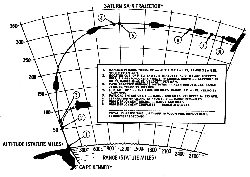
The trajectory of AS-103. (NASA Press Kit 65-38)
At T+8 seconds, AS-103 began a roll and pitch maneuver, taking it to a flight azimuth of 105°. The roll maneuver ended 15 seconds later. The Saturn I reached Mach 1 at T+54 seconds, and the maximum dynamic pressure (max Q) at T+66. The pitch program was completed at T+138. At T+140.22, the four inboard H-1 engines were cut off (IECO), and the outer engines, 5.34 seconds later (OECO). At this time, AS-103 had reached an altitude of 55 miles (89 kilometers), and was 44 miles (77 kilometers) downrange. It was traveling at 6,000 miles per hour (9,656 kilometers per hour).
The Saturn I first stage was jettisoned. Four solid fuel retro rockets were to slow the first stage, but one malfunctioned shortly after ignition. The first stage impacted the ocean surface at T+718.95, 961.29 kilometers (597.32 miles) down range. (N. 25.8155, W. 71.3491)
At T+148.12, the command to start the six RL10 engines of the second stage was sent. The two stages had separated by 10.95 meters (35.93 feet) at engine ignition. (the minimum requirement was 3 meters/9.8 feet.) Ten seconds later, the Launch Escape System was jettisoned.
After about 8 minutes, at T+631.659, the S-IV-9 engines were cut off and the vehicle was inserted into orbit 1,200 miles, (1,931 kilometers) downrange, with a velocity of 8,091.1 meters per second (29,128 kilometers per hour/18,099 miles per hour).
At T+813, the Command and Service Module was separated, and at T+863.4, the Pegasus wings began to deploy. This took 39.6 seconds. These panels had an overall span of 96 feet (29.261 meters) and width of 14 feet (4.267 meters). They carried 208 detector panels. Each panel was 3 feet, 4 inches × 1 foot, 8 inches × 1 inch (1.016 x 0.508 x 0.0254 meters).
A 50-second video of this evolution can be seen on YouTube at:
Pegasus I stabilized in a 430.00 × 523.00 kilometer (267.19 × 329.33 miles) elliptical orbit with a period of 94.10 minutes. As residual fuel (approximately 700 pounds) from the S-IV second stage, which remained attached to the satellite, vented, Pegasus began to tumble.
Pegasus I had about eighty times the detecting area than the Explorer I satellite, which had been launched 31 January 1958. By late May 1965, more than 70 meteoroid hits had been detected.
NASA issued a contract to build three Pegasus satellites, two for flight and third as a backup, to the Fairchild Stratos Corporation in February 1963. (Fairchild Hiller Corporation after 1964.) Final assembly took place at the Aircraft-Missiles Division, Hagerstown, Maryland. (In fact, all three were launched.) Pegasus A was transported by aircraft and arrived at Cape Kennedy Air Force Station on 20 December 1964.
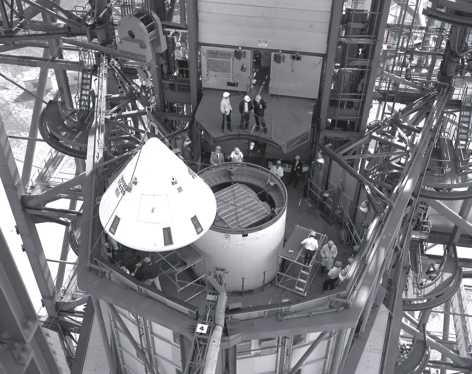
“In this photograph, the Pegasus, meteoroid detection satellite is installed in its specially modified Apollo service module atop the S-IV stage (second stage) of a Saturn I vehicle for the SA-9 mission at Cape Kennedy. Personnel in the service structure moved the boilerplate Apollo command module into place to cap the vehicle. The command and service modules, visible here, were jettisoned into orbit to free the Pegasus for wing deployment. The SA-9 was launched on February 16, 1965.” (NASA)
When stored inside the boiler plate command and service module, the satellite was 17 feet, 4 inches (5.283 meters) long, 7 feet, 0 inches (2.134 meters) wide, and 9.5 inches (24.13 centimeters) deep.
Pegasus I was deactivated 29 August 1968. Its orbit decayed and it reentered the Earth’s atmosphere 17 September 1978. BP-16, the boilerplate Apollo CSM, remained in orbit until 10 July 1985.
Diagram from “RESULTS OF THE EIGHTH SATURN I LAUNCH VEHICLE TEST FLIGHT SA-9” MPR-SAT-FE-66-4, at Page 97)
AS-103 consisted of a Saturn I Block II first stage, S-I-9; a S-IV second stage, S-IV-9; a boilerplate Apollo Command and Service Module, BP-16; with a Launch Escape System tower. It had a height of approximately 57.3 meters (187.99 feet). It weighed 1,110,941 pounds (503,914 kilograms) at First Motion, including 878,179 pounds (398,335 kilograms) of propellant.
S-I-9 was the last Saturn S-I first stage to be built at NASA’s Marshall Space Flight Center in Huntsville, Alabama. (SA-8, SA-10, and the following Saturn first stage boosters were produced by the Chrysler Corporation Space Division at NASA’s Michoud Assembly Facility in New Orleans, Louisiana.) The Block II variant was modified for use by the United States Air Force to launch it’s proposed X-20 Dyna-Soar manned orbital vehicle. The most visible modification are the very large fins for enhanced stability, along with four smaller stub fins. These fins extended radially 9 feet (2.7 meters) from the thrust structure, and each had a surface area of 121 square feet (11.24 square meters). S-I-9 was barged to the Cape Kennedy Air Force Station, arriving there 30 October 1964.
Saturn I Block II first stage. 1. TV Camera, 2. Movie Camera, 3. Hydrogen Chill-Down Duct, 4. Cable Tunnel, 5. Four Turbine Exhaust Ducts, 6. Four Stub Fins, 7. Eight H-1 Engines, 8. Four Fins, 9. Heat Shield, 10. Firewall, 11. Anti-Slosh Baffles, 12. One 105-inch (2.667 meters) Diameter LOX Tank, 12. Anti-Slosh Baffles Eight 70-inch (1.778 meters) diameter Tanks, 13. Instrument Compartment (typical F-1 & F-2), 14. Four Retro-Rockets. (NASA MSFC-9801761)
S-I-9 was 80.3 feet (20.275 meters) long and 21.4 feet (6.523 meters) in diameter. Eight Redstone 5 feet, 10 inch (1.778 meters) diameter rocket fuel tanks, with four containing the RP-1 fuel, and four filled with liquid oxygen, surrounded a 8 feet, 9 inch (2.667 meter) diameter Jupiter rocket fuel tank containing liquid oxygen. The stage was powered by eight uprated Rocketdyne H-1 engines. The eight engines produced 1,500,000 pounds of thrust (6,672 kilonewtons) at Sea Level.
The Saturn S-IV-9 second stage was built by the Douglas Aircraft Company’s Missile & Space Division, Huntington, Beach, California. It was 41.5 feet (12.65 meters) long and 18.5 feet (5.64 meters) in diameter and had an empty weight of about 14,000 pounds (6,350 kilograms). It carried 100,386 pounds (45,534 kilograms) of propellant. The stage was powered by six Pratt & Whitney RL10A-3 rocket engines. The six engines produced 88,976 pounds of thrust (395.785 kilonewtons). The stage was coated with a special heat resistant paint developed by the Illinois Institute of Technology, Chicago. The S-IV stage was transported by aircraft and arrived at the Cape Kennedy Air Force Station 23 October 1964.
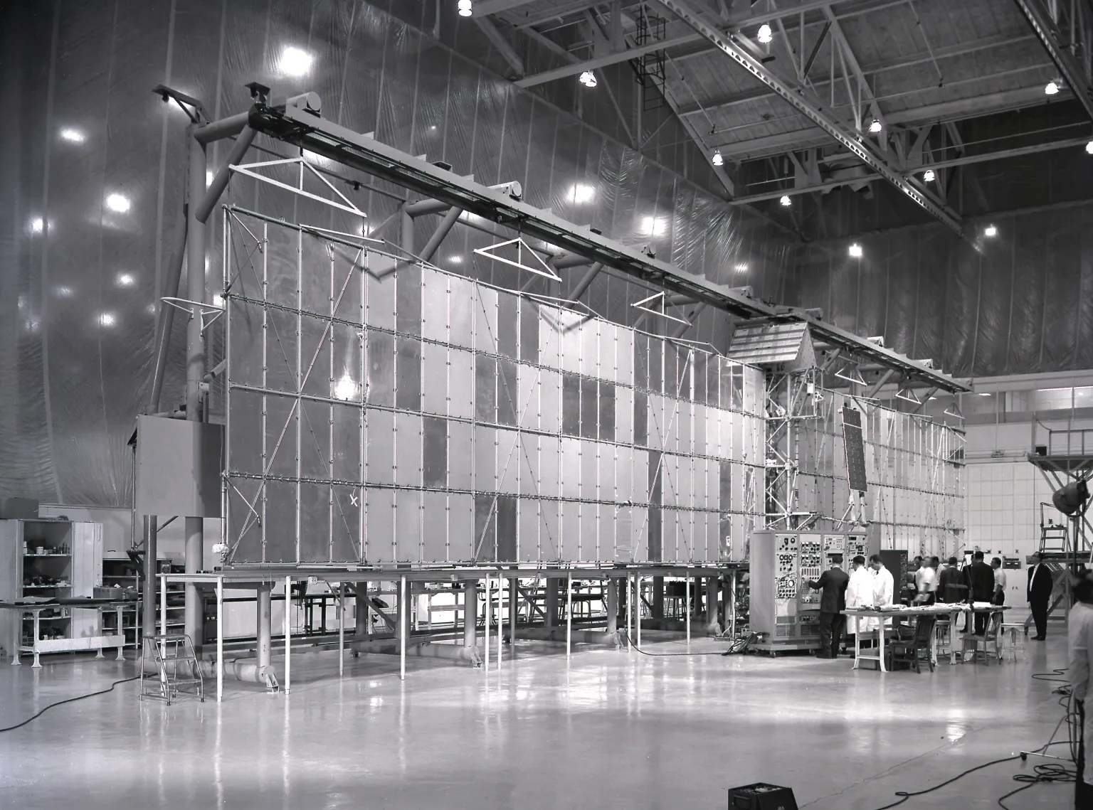
Pegasus Deployment Sequence (NASA) “Fairchild technicians check out the extended Pegasus meteoroid detection surface. The Pegasus was developed by Fairchild Stratos Corporation, Hagerstown, Maryland, for NASA through the Marshall Space Flight Center. After being placed into orbit around the Earth, the satellite unfolded a series of giant panels to form a pair of wings measuring 96 feet across.” (NASA)
NASA considered the Saturn S-I series to be remarkably successful. Up to this time, new rockets failed at a rate of 50% during two to three dozen tests.
Gemini VII/Titan II GLV-7 lifts off from Launch Complex 19, 1430 EST, 4 December 1965. (NASA)
4 December 1965, 19:30:03.702 UTC: At 2:30 p.m., Eastern Standard Time, Gemini VII/Titan II GLV-7 lifted of from Launch Complex 19 at the Cape Kennedy Air Force Station, Cape Kennedy, Florida. On board were Major Frank F. Borman II, United States Air Force, the mission command pilot, and Lieutenant Commander James A. Lovell, Jr., United States Navy, pilot. During the climb to Earth orbit, the maximum acceleration reached was 7.3 Gs.
Gemini VII was placed into Earth orbit at an initial maximum altitude (apogee) of 177.1 nautical miles (327.8 kilometers) and a minimum (perigee) of 87.2 nautical miles (161.5 kilometers), at a velocity of 16,654.1 miles per hour (26,802.2 kilometers per hour), relative to Earth.
This mission was a planned 14-day flight which would involve an orbital rendezvous with another manned spacecraft, Gemini VI-A. The actual total duration of the flight was 330 hours, 35 minutes, 1 second.
Artist’s concept of Gemini spacecraft, 3 January 1962. (NASA-S-65-893)
The two-man Gemini spacecraft was built by the McDonnell Aircraft Corporation of St. Louis, Missouri, the same company that built the earlier Mercury space capsule. The spacecraft consisted of a series of cone-shaped segments forming a reentry module and an adapter section. It had an overall length of 18 feet, 9.84 inches (5.736 meters) and a maximum diameter of 10 feet, 0.00 inches (3.048 meters) at the base of the equipment section. The reentry module was 11 feet (3.353 meters) long with a maximum diameter of 7 feet, 6.00 inches (2.347 meters). The Gemini re-entry heat shield was a spherical section with a radius of 12 feet, 0.00 inches (3.658 meters). The weight of the Gemini spacecraft varied from ship to ship. Gemini VII had a gross weight of 8,076.10 pounds (3,663.26 kilograms) at launch. It was shipped from St. Louis to Cape Kennedy in early October 1965.
Gemini VII, photographed in Earth orbit from Gemini VI-A, 15–16 December 1965. (NASA)
The Titan II GLV was a “man-rated” variant of the Martin SM-68B intercontinental ballistic missile. It was assembled at Martin Marietta’s Middle River, Maryland, plant so as not to interfere with the production of the ICBM at Denver, Colorado. Twelve GLVs were ordered by the Air Force for the Gemini Program. The GLV-7 first and second stages were shipped from Middle River to Cape Kennedy on 9 October 1965.
The Titan II GLV was a two-stage, liquid-fueled rocket. The first stage was 70 feet, 2.31 inches (21.395 meters) long with a diameter of 10 feet (3.048 meters). It was powered by an Aerojet Engineering Corporation LR87-7 engine which combined two combustion chambers and exhaust nozzles with a single turbopump unit. The engine was fueled by Aerozine 50, a hypergolic 51/47/2 blend of hydrazine, unsymetrical-dimethyl hydrazine, and water. Ignition occurred spontaneously as the components were combined in the combustion chambers. The LR87-7 produced approximately 430,000 pounds of thrust (1,912.74 kilonewtons). It was not throttled and could not be shut down and restarted. Post flight analysis indicated that the first stage engine of GLV-7 had produced an average of 462,433 pounds of thrust (2,057.0 kilonewtons). The second stage was 25 feet, 6.375 inches (7.031 meters) long, with the same diameter, and used an Aerojet LR91 engine which produced approximately 100,000 pounds of thrust (444.82 kilonewtons), also burning Aerozine 50. GLV-7’s LR91 produced an average of 102,584 pounds of thrust (456.3 kilonewtons).
The Gemini/Titan II GLV-7 combination had a total height of 107 feet, 7.33 inches (32.795 meters) and weighed 346,228 pounds (157,046 kilograms) at ignition.
Lieutenant Commander James A. Lovell, Jr., U.S. Navy, and Major Frank F. Borman II, U.S. Air Force, with a scale model of a Gemini spacecraft. (NASA)


")
")


")
")