Republic YF-105A-1-RE 54-098. (U.S. Air Force)Republic Aviation test pilot Russell M. “Rusty” Roth. (Jet Pilot Overseas)
22 October 1955: At Edwards Air Force Base, in the high desert of southern California, Republic Aviation Corporation test pilot Russell M. (“Rusty”) Roth took the first of two prototype YF-105A-1-REs, serial number 54-098, for its first flight.
Though equipped with an under-powered Pratt & Whitney J57-P-25 interim engine, the new airplane was able to reach Mach 1.2 in level flight.
Aerodynamic improvements to the engine intakes and redesign of the fuselage to incorporate the drag-reducing “area rule,” along with the more powerful J75-P-5 turbojet engine allowed the production model F-105B to reach Mach 2.15.
The first of two Republic YF-105A-1-RE Thunderchief prototypes, 54-098, on Rogers Dry Lake, Edwards Air Force Base, California, 1955. (U.S. Air Force)
The Thunderchief is the largest single-place, single-engine aircraft ever built. It was a Mach 2 fighter-bomber, designed for NATO defensive tactical nuclear strikes with a nuclear bomb carried in an internal bomb bay. The YF-105A was 61 feet, 0 inches (18.593 meters) long, with a wing span of 34 feet, 11 inches (10.643 meters) and overall height of 17 feet, 6 inches (5.334 meters). Its empty weight was 20,454 pounds (9,277 kilograms) and the Maximum Takeoff Weight (MTOW) was 41,500 pounds (18,824 kilograms).
The Pratt & Whitney Turbo Wasp JT3C (J57-P-25) was a two-spool axial-flow turbojet engine with a 16-stage compressor section (9 low- and 7 high-pressure stages) and a 3-stage turbine (1 high- and 2 low-pressure stages). The J57-P-25 had a Normal Power rating of 8,700 pounds of thrust (38.700 kilonewtons), and at Military Power produced 10,200 pounds of thrust (45.372 kilonewtons) (30-minute limit). The Maximum Power rating was 16,000 pounds of thrust (71.172 kilonewtons) with afterburner (5-minute limit). The J57-P-25 was 22 feet, 3.1 inches (6.784 meters) long, 3 feet, 3.8 inches (1.011 meters) in diameter, and weighed 5,120 pounds (2,322 kilograms).
The YF-105A’s wings were swept 45° at 25% chord. The angle of incidence was 0° and there was no twist. The wings had 3° 30′ anhedral. The total wing area was 385 square feet (35.8 square meters).
During testing, the prototype’s maximum speed was 770 knots (886 miles per hour (1,426 kilometers per hour) at 35,000 feet (10,668 meters)—Mach 1.34—and 676 knots (778 miles per hour/1,252 kilometers per hour) at Sea Level—Mach 1.02. The YF-105A’s service ceiling was 52,050 feet (15,865 meters). It’s combat radius was 950 nautical miles (1,093 statute miles/1,759 kilometers), and the maximum ferry range was 2,321 nautical miles (2,671 statute miles/4,298 kilometers).
Republic YF-105A 54-098 landing at Edwards Air Force Base. (Ray Wagner Collection, San Diego Air and Space Museum Archives)
The Thunderchief was armed with a General Electric T171E2 (M61) 20 mm six-barrel rotary cannon with 1,030 rounds of ammunition. 8,000 pounds (3,629 kilograms) of bombs could be carried in an internal bomb bay or on external hardpoints. A single free-fall B28IN variable-yield thermonuclear bomb could be carried in the bomb bay.
On 16 December 1955, YF-105A 54-098 made an emergency landing at Edwards AFB after one of its main landing gear assemblies was torn off when it failed to retract during a high speed flight. The pilot, Rusty Roth, was severely injured, but he survived. The prototype was shipped back to Republic for repair, but the cost was determined to be prohibitive.
Though designed for air-to-ground attack missions, F-105s are officially credited with 27.5 victories in air combat.
833 Thunderchiefs were built by Republic between 1955 and 1964. 334 of those were lost to enemy action during the Vietnam War. The F-105 remained in service with the United States Air Force until 1980, and with a few Air National Guard units until 1983.
Republic F-105D-5-RE Thunderchief 58-1173 carrying a bomb load of sixteen 750-pound M117 general purpose bombs. (U.S. Air Force)
Northrop YB-49 42-102367 takes off from Northrop Field, Hawthorne, California. (U.S. Air Force)
21 October 1947: At Northrop Field, Hawthorne, California, Northrop Corporation Chief Test Pilot Max R. Stanley took off in the first YB-49, 42-102367, and flew it to Muroc Air Force Base for flight testing. The co-pilot was Fred C. Bretcher and Orva H. Douglas served as flight test engineer. The Flying Wing landed at Muroc 34 minutes later.
(Pasadena Star-News, 26 October 1947, Page 40, Columns 2–4)
An estimated 4,000 spectators lined the streets surrounding Northrop Field. The YB-49 was escorted by a Lockheed P-80A Shooting Star and a Northrop P-61 Black Widow as it climbed to 10,000 feet (3,048 meters) en route to Muroc. Over Lancaster, California, the P-61 caught fire and was abandoned by its crew.
42-102367 had been converted from the second YB-35 pre-production test aircraft. The original Flying Wing’s four Pratt & Whitney Wasp Major (R-4360-21) radial engines were replaced by turbojet engines and several aerodynamic improvements were made.
Chief Test Pilot Max R. Stanley. (Photograph courtesy of Neil Corbett, Test and Research Pilots, Flight Test Engineers)
The YB-49 was a very unusual configuration for an aircraft of that time. There was no fuselage or tail control surfaces. The crew compartment, engines, fuel, landing gear and armament were contained within the wing. Air intakes for the turbojet engines were placed in the leading edge and the exhaust nozzles were at the trailing edge. Four small vertical fins for improved yaw stability were also at the trailing edge.
Northrop YB-49 42-102367 at Northrop Field, Hawthorne, California. (Unattributed)
The YB-49 had a length of 53 feet, 1 inch (16.180 meters), wingspan of 172 feet (52.426 meters) and overall height of 15 feet, 2 inches (4.623 meters). It weighed 88,442 pounds (40,117 kilograms) empty and its Maximum Takeoff Weight (MTOW) was 193,938 pounds (87,969 kilograms).
The Wing defined the airplane. The leading edge was swept aft 26° 57′ 48″, and the trailing edge, 10° 15′ 22″. The wing’s total area was 4,000 square feet (371.6 square meters). It had an aspect ratio of 7.4:1. At the root, the chord was 37 feet, 6 inches (11.430 meters), tapering to 9 feet, 4 inches (2.844 meters) at the tip. There was 0° angle of incidence at the root, -4° at the wing tips, and 0° 53′ dihedral.
Northrop YB-49 42-102367 in flight near Muroc Air Force Base. (U.S. Air Force)
The YB-49 was powered by eight General Electric-designed, Allison Engine Company-built J35-A-5 engines. (This same engine variant was used in the North American Aviation XP-86, replacing its original Chevrolet-built J35-C-3.) The engines were later upgraded to J35-A-15s. The J35 was a single-spool, axial-flow turbojet engine with an 11-stage compressor and single-stage turbine. The J35-A-15 had a Normal Power rating of 3,270 pounds of thrust (14.546 kilonewtons) at 7,400 r.p.m. The Military Power rating was 3,750 pounds (16.681 kilonewtons) at 7,700 r.p.m. The engine was 14 feet, 0.0 inches (4.267 meters) long, 3 feet, 4.0 inches (1.016 meters) in diameter and weighed 2,400 pounds (1,089 kilograms).
The YB-49 had four vertical fins extending above and below the trailing edge of the Wing. (U.S. Air Force 090706-F-1234K-048)
During testing the YB-49 reached a maximum speed of 428 knots (493 miles per hour/793 kilometers per hour) at 20,800 feet (6,340 meters). Cruise speed was 365 knots (429 miles per hour/690 kilometers per hour). The airplane had a service ceiling of 49,700 feet (15,149 meters). The YB-49 had a maximum fuel capacity of 14,542 gallons (55,047 liters) of JP-1 jet fuel. Its combat radius was 1,403 nautical miles (1,615 statute miles/2,598 kilometers).
The maximum bomb load of the YB-49 was 16,000 pounds (7,257 kilograms), though the actual number of bombs was limited by the volume of the bomb bay and the capacity of each bomb type. While the YB-35 Flying Wing was planned for multiple machine gun turrets, the YB-49 carried no defensive armament.
Northrop YB-49 42-102367 takes off from Northrop Field, Hawthorne, California. Note the crowds of onlookers and residential housing along W. 120th Street, on the north side of the airport. (Unattributed)
Only two Northrop YB-49s were built and they were tested by Northrop and the Air Force for nearly two years. Though an additional nine YB-35s were ordered converted, the B-49 was not placed into production.
A Northrop YB-49 with a Boeing XB-47 Stratojet. (U.S. Air Force)
The second ship, YB-49 42-102368, disintegrated in flight during a test flight north of Muroc Air Force Base, 5 June 1948, killing the entire crew, which included Captain Glen Edwards. The name of Muroc was changed to Edwards Air Force Base in his honor.
YB-49 42-102367 was destroyed by fire following a taxiing accident at Edwards, 15 March 1950. The program was cancelled on the same day.
The Bell XH-40 prototype, 55-4459, hovering in ground effect at the Bell Aircraft Corporation helicopter plant at Hurst, Texas. The helicopter’s stabilizer bar, doors and cowlings are not installed in this photograph. (Niagara Aerospace Museum)
20 October 1956: Bell Aircraft Corporation Chief Pilot Floyd W. Carlson and Chief Experimental Test Pilot Elton J. Smith made the first flight of the Bell Model 204 (designated XH-40-BF serial number 55-4459 by the United States Army) at Bell’s helicopter factory in Hurst, Texas.
The XH-40 is a six-place, turboshaft-powered light helicopter, designed with a primary mission of battlefield medical evacuation. Operated by one or two pilots, it could carry four passengers, or two litter patients with an attendant. The prototype’s fuselage was 39 feet, 3.85 inches (12.294 meters) long. The overall length of the helicopter with rotors turning was 53 feet, 4.00 inches (16.256 meters). The height (to the top of the tail rotor arc) is 14 feet, 7.00 inches (4.445 meters). The empty weight of the XH-40 was 3,693 pounds (1,675 kilograms), with a maximum gross weight of 5,650 pounds (2,563 kilograms).
Bell XH-40 first flight. (U.S. Army)
The two blade semi-rigid, under-slung main rotor had a diameter of 44 feet, 0.00 inches (12.294 meters), and turned counter clockwise when viewed from above. (The advancing blade is on the helicopter’s right.) The blades used a symmetrical airfoil. They had a chord of 1 foot, 3.00 inches (0.381 meters) and 10° negative twist. The main rotor hub incorporated pre-coning. At 100% NR, the main rotor turned 324 r.p.m. The two blade tail rotor assembly had a diameter of 8 feet, 6.00 inches (2.591 meters). It was mounted on the left side of the pylon in a pusher configuration and turned counter-clockwise as seen from the helicopter’s left. (The advancing blade is above the axis of rotation.)
Bell XH-40 55-4459 with cowlings and rear doors installed. (U.S. Army)
The prototype XH-40 was powered by a Lycoming LTC1B-1 (XT53-L-1) free-turbine (turboshaft). The engine uses a 5-stage axial-flow, 1-stage centrifugal-flow compressor with a single-stage gas producer turbine and single-stage power turbine. A reverse-flow combustion section with 12 burners allows a significant reduction in the the engine’s total length. The XT53L-1 had a Maximum Continuous Power rating of 770 shaft horsepower, and Military Power rating of 825 shaft horsepower. It could produce 860 shaft horsepower at 21,510 r.p.m. At Military Power, the XT53-L-1 produced 102 pounds of jet thrust (0.454 kilonewtons). The power turbine drives the output shaft through a 3.22:1 gear reduction. The T53-L-1 is 3 feet, 11.8 inches (1.214 meters) long and 1 foot, 11.25 inches (0.591 meters) in diameter, and weighs 460 pounds (209 kilograms).
A Lycoming XT53-L-1 turboshaft engine installed on the first Bell XH-40 prototype, at Hurst, Texas, 10 August 1956. (University of North Texas Libraries, Special Collections)
The XH-40 had a maximum speed of 133 knots (153 miles per hour/246 kilometers per hour) at 2,400 feet (732 meters), and 125 knots (144 miles per hour/232 kilometers per hour) at 5,000 feet (1,524 meters). The in-ground-effect hover ceiling (HIGE) was 17,300 feet (5,273 meters) and the service ceiling was 21,600 feet (6,584 meters). The helicopter’s fuel capacity was 165 gallons (625 liters), giving it a maximum range of 212 miles (341 kilometers).
Three XH-40 prototypes were built, followed by six YH-40 service test aircraft. The designation of the XH-40 was soon changed to XHU-1.
This helicopter was the prototype of what would be known world-wide as the “Huey.” The helicopter was designated by the U.S. Army as HU-1, but a service-wide reorganization of aircraft designations resulted in that being changed to UH-1. Produced for both civil and military customers, it evolved to the Model 205 (UH-1D—UH-1H), the twin-engine Model 212 (UH-1N), the heavy-lift Model 214, and is still in production 66 years later as the twin-engine, four-bladed, glass-cockpit Model 412EPI and the Subaru Bell EPX.
Left rear quarter view of the Bell XH-40 hovering in ground effect at the Bell Aircraft Corporation helicopter plant at Hurst, Texas. (U.S. Army)
Sources differ as to the date of the first flight, with some saying 20 October, and at least one saying 26 October, but most cite 22 October 1956. This individual aircraft is at the U.S. Army Aviation Museum, Fort Rucker, Alabama. The museum’s director, Robert S. Maxham, informed TDiA that, “The earliest and only historical record cards that we have on 4459 are dated 2 MAY 1958, and at that time the aircraft had 225.8 hours on it.” The Smithsonian Institution National Air and Space Museum, a generally reliable source, states the first flight was 22 October 1956.
Many sources also state the the XH-40 first flew on the same day on which Lawrence D. Bell died, which was 20 October.
The earliest contemporary news report yet discovered by TDiA, states,
On October 20, after several hours of ground running, the new Bell XH-40 helicopter was flown for the first time.
—FLIGHT and AIRCRAFT ENGINEER, No. 2506, Vol. 71, Friday, 1 February 1957, Page 136, at Column 1
A rare color photograph of of a prototype Bell XH-40, hovering in ground effect. In this photo, a stabilizer bar is installed, and the synchronized elevator has end plates similar to those on Bell Model 47 helicopters. (Unattributed)
Beginning in 2015, XH-40 55-4459 was restored by Blast Off, Inc., at Atmore, Alabama. It was then returned to the Army Aviation Museum.
Bell XH-40 55-4459 ready for transport to Blast Off, Inc., 16 June 2015. (The Atmore Advance)The Bell XH-40 at the United States Army Aviation Museum.
Douglas X-3 49-2892. Rogers Dry Lake is in the background. (NASA)
20 October 1952: At Edwards Air Force Base, California, Douglas Aircraft Company test pilot William Barton (“Bill”) Bridgeman made the first test flight of the X-3 twin-engine supersonic research airplane. During a high-speed taxi test five days earlier, Bridgeman and the X-3 had briefly been airborne for approximately one mile over the dry lake bed, but on this flight he spent approximately 20 minutes familiarizing himself with the new airplane.
William Barton “Bill” Bridgeman, 1916–1968. (Loomis Dean/LIFE Magazine)
Bill Bridgeman had been a Naval Aviator during World War II, flying the Consolidated PBY Catalina and PB4Y (B-24) Liberator long range bombers with Bombing Squadron 109 (VB-109), “The Reluctant Raiders.”
Bridgeman stayed in the Navy for two years after the war, then he flew for Trans-Pacific Air Lines in the Hawaiian Islands and Southwest Airlines in San Francisco, before joining Douglas Aircraft Co. as a production test pilot. He checked out new AD Skyraiders as they came off the assembly line at El Segundo, California. He soon was asked to take over test flying the D-558-2 Skyrocket test program at Muroc Air Force Base (now, Edwards AFB.) With the Skyrocket, he flew higher—79,494 feet (24,230 meters)—and faster—Mach 1.88—than any pilot had up to that time.
Douglas X-3 parked on Rogers Dry Lake, 1956 (NASA)
The Douglas X-3, serial number 49-2892, was built for the Air Force and NACA to explore flight in the Mach 1 to Mach 2 range. It was radically shaped, with a needle-sharp nose, very long thin fuselage and small straight wings. The X-3 was 66 feet, 9 inches (20.345 meters) long, with a wing span of just 22 feet, 8.25 inches (6.915 meters). The overall height was 12 feet, 6.3 inches (3.818 meters). The X-3 had an empty weight of 16,120 pounds (7,312 kilograms) and maximum takeoff weight of 23,840 pounds (10,814 kilograms).
It was to have been powered by two Westinghouse J46 engines, but when those were unsatisfactory, two Westinghouse XJ34-WE-17 engines were substituted. This was an axial flow turbojet with an 11-stage compressor and 2-stage turbine. It was rated at 3,370 pounds (14.99 kilonewtons) of thrust, and 4,900 pounds (21.80 kilonewtons) with afterburner. The XJ34-WE-17 was 14 feet, 9.0 inches (4.496 meters) long, 2 feet, 1.0 inch (0.635 meters) in diameter and weighed 1,698 pounds (770 kilograms).
The X-3 had a maximum speed of 706 miles per hour (1,136 kilometers per hour) and a service ceiling of 38,000 feet (11,582 meters).
This view of the Douglas X-3 shows its very small wings and tail surfaces. (NASA)
The X-3 was very underpowered with the J34 engines and could just reach Mach 1 in a shallow dive. Its highest speed, Mach 1.208, required a 30° dive. The research airplane was therefore never able to be used in flight testing in the supersonic speed range for which it was designed. Because of its design characteristics, though, it became useful in exploring stability and control problems encountered in the transonic range.
Two X-3 aircraft had been ordered from Douglas, but only one completed.
In addition to Bill Bridgeman, the Douglas X-3 was flown by Air Force test pilots Major Chuck Yeager and Lieutenant Colonel Frank Everest, and NACA High Speed Flight Station research pilot Joseph A. Walker.
NACA flight testing began in August 1954. On the tenth flight, 27 October, Joe Walker put the X-3 into abrupt left aileron rolls at 30,000 feet (9,144 meters), first at 0.92 Mach and then at Mach 1.05. Both times, the aircraft violently yawed to the right and then pitched down.
This was a new and little understood condition called inertial roll coupling. It was a result of the aircraft’s mass being concentrated within its fuselage, the torque reactions and gyroscopic effect of the turbojet engines and the inability of the wings and control surfaces to stabilize the airplane and overcome its rolling tendency. (Just two weeks earlier, North American Aviation’s Chief Test Pilot George S. Welch had been killed when the F-100A Super Sabre that he was testing also encountered inertial roll coupling and disintegrated.) A post-flight inspection found that the X-3 had reached its maximum design load. The X-3 was grounded for the next 11 months.
Joe Walker resumed flight testing the X-3 in 1955. It’s last flight was 23 May 1956. After the flight test program came to an end, the X-3 was turned over to the National Museum of the United States Air Force, Wright-Patterson Air Force Base, Ohio.
Douglas X-3 49-2892 at the National Museum of the United States Air Force. (NASM)
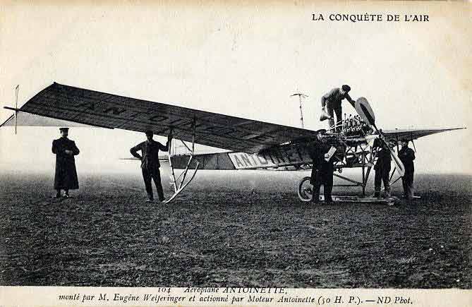
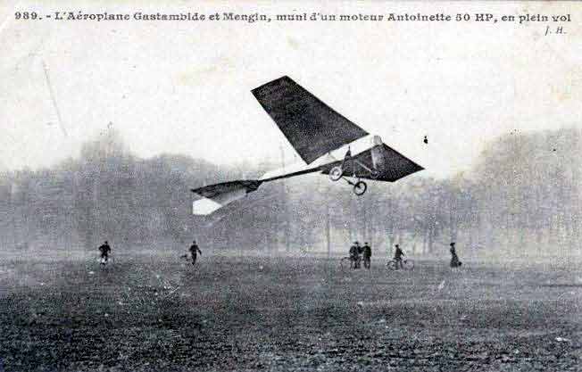
Eugène Welferinger à bord de l’Antoinette IV : [photographie de presse] / [Agence Rol]19 October 1908: From the grounds of the Château de Bagatelle, Paris, France, Eugène Welferinger (1872–1936) made the first flight of the Société d’aviation Antoinette monoplane, the Antoinette IV.
A single-place, single-engine airplane, the Antoinette IV was one the first successful monoplanes. American Machinist described it as a “purely racing machine.”
The airplane and its V-8 engine were designed by Léon Levavasseur. It was modified a number of times, as was its sister ship, the Antoinette V.
“Left front view of Société Antoinette ‘Antoinette IV’ on the ground. This version is of ‘Antoinette IV’ is fitted with two large in-line wheels, substantial mid-wing skids, and a paddle-type propeller. Designer Léon Levavasseur stands at left (bearded man wearing dark vest and cap). Issy-les-Moulineaux, Paris, France, November 1908.” (M. Rol & Cie, 4 Rue Richer, Paris/Library of Congress)
Augustus Post, Secretary of the Aero Club of America, wrote in the weekly technical publication, American Machinist:
M. Levavasseur considered that the monoplane offered the advantages of simplicity of form, natural stability, and was easier to construct; that is to say, that the thrust of the motor required for flight was less under the same conditions of speed and weight.
The “Antoinette” is particularly interesting on account of the manner in which the problems have been studied and the great amount of thought that has been given to them. The machine is perhaps without question the most finely finished of those in its class, shows the most careful workmanship in its most minute detail, and presents more new and original features than any of the other machines which may be compared with it. It also provides a comfortable cockpit for the aviator, a distinct advantage in long and trying flights.
—American Machinist, Hill Publishing Company, New York, 7 October 1909, Page 608 at Column 2
Antoinette IV, right front quarter view. (Phototeque chronorama)Antoinette IV, front view. (Geneanet)
The Antoinette IV was approximately 11,50 mètres (37.72966 feet) long with a wingspan of 14,80 mètres (48.55643 feet). The leading edge was swept aft 3°. They had a chord of 3 meters (9.8 feet) at the root, tapering to 2 meters (6.6 feet) at the tip. The wing had an angle of incidence of 4° with 6° dihedral. The total surface area was 34 square meters (366 square feet). The weight of the Antoinette IV was 460 kilograms (1,014 pounds) with one hour of fuel. It was capable of reaching 120 kilometers per hour (75 miles per hour).
Antoinette IV in an early configuration. (La Phototeque de Chonorama)
The airplane was described in contemporary reports as “beautiful” and often mentioned was the very narrow triangular cross section of its fuselage. Different configurations of landing gear were tried, with combinations of skids and wheels, wheels in tandem, and side-by-side. Directional control was created through “wing-warping” as had been used by the Wright Brothers. This was later modified to an aileron system. The tail surfaces were cruciform, with two triangular rudders located above and below the triangular elevator. Flight controls were four hand wheels and two pedals which connected to the control surfaces by cables.
An unidentified Antoinette employee with Hubert Latham (center) and Léon Levavasseur (right), The airplane is the Antoinette IV. (Librairie Militaire Guérin Mourmelon, via Old Machine Press)
As originally built, the Antoinette IV was powered by a steam-cooled, normally-aspirated, 7.274 liter (443.861 cubic inch displacement) Antoinette 8V 90° overhead valve V-8 engine which produced approximately 45–50 chaval-vapeur (44.4–49.3 horsepower) at 1,400 r.p.m. This engine was considerably smaller and lighter than Levavasseur’s previous V-8s. Because the compression ratio was increased, the aluminum cylinder heads were replaced with forged steel heads. Carburetors were used instead of direct injection, which was prone to clogging. The 8V was a direct-drive engine which turned a propeller with two aluminum blades which were riveted to a steel tube that attached to the engine’s output shaft. The propeller had a diameter of 2.20 meters (7 feet, 2.6 inches). The V-8 engine was 0.750 meters (2 feet, 5.5 inches inches) long, 0.600 meters (1 foot, 11.6 inches) wide and (0.600 meters (1 foot, 11.6 inches) high. It weighed 60 kilograms (132 pounds), dry, and 85 kilograms (187 pounds) in running order.
Two-view drawing of an early configuration of Léon Levavasseur’s Antoinette Monoplane. (Flight, Vol. I, No. 43, 23 October 1909, at Page 663)
The engine sold for ₣12,500 (approximately $2,451 U.S. dollars) with delivery expected in 10 months. Antoinette airplanes could be purchased for ₣25,000, or about $4,902 U.S. dollars.
On 19 July 1909, Arthur Louis Hubert Latham, who had been taught to fly by Welféringer, attempted to fly the Antoinette IV across the English Channel, but an engine failure forced it down about 8 miles (13 kilometers) off the French coast.
Hubert Latham is rescued from the English Channel by the crew of the French torpedo boat destroyer, Harpon, 19 July 1909. (hydroretro)
The airplane remained afloat and Latham was rescued by the French torpedo boat destroyer FS Harpon, but the airplane was severely damaged during the recovery.
Léon Lavavasseur, circa 1905. (National Aviation Museum/CORBIS)
Léon Levavasseur was a French engineer, born 8 January 1863 near Cherbourg, France. He invented the 90° V-8 engine, which he patented in 1902. He specialized in lightweight engines, using components designed to be only as strong as was required by their specific use. He developed direct fuel injection and evaporative cooling for internal combustion engines.
Mlle. Antoinette Gastambide, namesake of the Antoinette IV and the company that built it. (L’Aérophile)
His company, Société d’aviation Antoinette, and its products, were named for the daughter of his business partner, Jules Gastambide. The company initially produced lightweight engines for other airplane builders, but began to construct complete airplanes in 1906. Both Levavasseur and Gastambide left Antoinette in 1909 following a disagreement with the board of directors, but they returned five months later. The company failed in 1911.
Levavasseur was appointed Chevalier de la légion d’honneur in 1909.
Léon Levavasseur died in Paris, France, 26 February 1922, at the age of 59 years.
Recommended: An excellent article about Léon Levavasseur’s Antoinette engines can be found at Old Machine Press:


 hover, right front quarter, low oblique view. All doors and cowlings have been removed. (U.S. Army)")
")


 hover, left rear quarter view. All doors and cowlings have been removed. (U.S. Army)")


, close-up, LIFE Magazine")