The F-101A was a development of the earlier McDonnell XF-88 Voodoo and all were production aircraft. There were no prototypes.

Robert C. Little flew P-51 Mustang fighters during World War II. He joined McDonnell Aircraft Corporation as a test pilot in 1948. He flew the FH Phantom, and made the first flights of the F3H Demon, the F-101A Voodoo and the F-101B. He was next assigned as McDonnell’s chief test pilot and base manager at Edwards Air Force Base. He the made the first flight of the YF4H-1 Phantom II and conducted the early company tests of the airplane, then became the F4H program manager.
Outside the cockpit, Little rose through the company’s ranks and after the merger with Douglas, became a corporate vice president, overseeing the operations of McDonnell-Douglas at St. Louis and McDonnell-Douglas Helicopters at Mesa, Arizona.


The McDonnell F-101A Voodoo was a single-seat twin-engine supersonic interceptor. It was 67 feet, 5 inches (20.549 meters) long with a wingspan of 39 feet, 8 inches (12.090 meters) and overall height of 18 feet (5.486 meters). The total wing area was 368 square feet (34.19 square meters). The wings’ sweep was 36° 36′ at 25% chord. The angle of incidence was 1°. There was no twist or dihedral. The F-101A weighed 24,970 pounds (11,326 kilograms) empty and had maximum takeoff weight of 49,998 pounds (22,679 kilograms).
Power was supplied by two Pratt & Whitney J57-P-13 axial-flow turbojet engines. The J57 was a two-spool axial flow turbojet which had a 16-stage compressor (9 low- and 7 high-pressure stages), and a 3-stage turbine (1 high- and 2 low-pressure stages). The J57-P-13 maximum continuous power rating of 8,700 pounds of thrust (38.70 kilonewtons); military power, 10,200 pounds (45.37 kilonewtons) (30-minute limit); and 15,000 pounds (66.72 kilonewtons) with afterburner (5 minute limit). The -P-13 was 3 feet, 4.3 inches (1.024 meters) in diameter, 17 feet, 7.0 inches (5.359 meters) long, and weighed 5,025 pounds (2,279 kilograms).
The F-101A had a maximum speed of 866 knots (997 miles per hour/1,604 kilometers per hour) at 35,000 feet (10,668 meters). Its service ceiling was 45,800 feet (13,960 meters). The airplane’s combat radius was 1,011 nautical miles (1,163 statute miles/1,872 kilometers). The maximum ferry range was 2,541 nautical miles (2,924 statute miles/4,706 kilometers)
The Voodoo was armed with four 20mm M39 autocannons with 200 rounds of ammunition per gun. It could carry a single Mark 7, Mark 28 or Mark 43 tactical nuclear bomb.
Of 807 F-101 Voodoos built, 77 were F-101As.
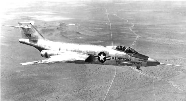

F-101A 53-2418 was transferred to General Electric for testing the J79 afterburning turbojet engine which would later power the McDonnell F-4 Phantom II. In this configration it was designated NF-101A. General Electric returned the Voodoo to the Air Force in 1959. By that time obsolete, it was used as a maintenance trainer at Shepard Air Force Base, Texas.
53-2418 was next turned over to a civilian aviation maintenance school and assigned a civil registration number by the Federal Aviation Administration, N9250Z. The airplane was sold as scrap, but was purchased by Mr. Dennis Kelsey. In 2009, Mrs. Kelsey had the airplane placed in the care of the Evergreen Aviation and Space Museum, McMinnville, Oregon. After being partially restored by Evergreen Air Center, Marana, Arizona, 53-2418 was placed on display at the Evergreen Museum.

© 2018, Bryan R. Swopes