The first prototype Mikoyan MiG 29A, 9-01, (“01 Blue”) on display at the Central Air Force Museum, Monino. (Detail from image by AVIA BavARia/Wikipedia)Alexander Vasilievich Fedotov
6 October 1977: The first of eleven prototypes of the Mikoyan MiG 29A fighter, 9-01, made its first flight at Ramenskoye Airfield with Chief Test Pilot Alexander Vasilievich Fedotov, Hero of the Soviet Union, in the cockpit.
Fedotov had been a test pilot at A.I. Mikoyan EDB since 1958 and set eighteen speed and altitude world records flying high performance aircraft. He was killed while testing the MiG 31 in 1984.
The MiG 29A is a fourth generation, single-seat, twin-engine, Mach 2+ air superiority fighter built by the Mikoyan Design Bureau. It entered service with the Soviet Union in 1983 and has been widely exported to many other nations. The MiG 29A is 13.37 meters (57 feet) long and has a wing span of 11.4 meters (37 feet, 3 inches). Its empty weight is 11,000 kilograms (24,250 pounds) and the maximum takeoff weight (MTOW) is 20,000 kilograms (44,100 pounds). The fighter is powered by two Klimov RD-33 turbofan engines which produce 11,240 pounds of thrust, or 18,277 pounds of thrust with afterburner. It has a maximum speed of Mach 2.25 (1,490 miles per hour/2,400 kilometers per hour) and a service ceiling of 59,100 feet (18,013 meters). Maximum range with internal fuel is 1,430 kilometers (888 miles).
Armament consists of one Gryazev-Shipunov GSh-301 30mm autocannon with 150 rounds of ammunition and a combination of air-to-air missiles, rockets or bombs carried on underwing pylons or fuselage hard points.
Alexander Vasilievich Fedotov born 23 June 1932 at Stalingrad, Russia (renamed Volgograd in 1961). He graduated from the Air Force Special School at Stalingrad, and in 1950, entered the Soviet Army. Fedotov attended the Armavir Military Aviation School of Pilots at Amravir, Krasnodar Krai, Russia, graduating in 1952, and then became a flight instructor. In 1958 he attended the Ministry of Indutrial Aviation Test Pilot School at Zhukovsky. He was a test pilot for the Mikoyan Experimental Design Bureau from 1958 to 1984. In 1983, Alexander Fedotov was promoted to the rank of Major General in the Soviet Air Force.
On 22 July 1966, Fedotov was honored as a Hero of the Soviet Union. He was named an Honored Test Pilot of the Soviet Union, 21 February 1969. He was qualified as a Military Pilot 1st Class. Fedotov was twice awarded the order of Lenin, and also held the Order of the Red Banner and the Order of the Red Banner of Labor.
During his career as a test pilot, Major General Fedotov had been forced to eject from an airplane three times. He had also set 15 Fédération Aéronautique Internationale world records for speed, altitude and time to altitude. One of these, FAI Record File Number 2825, in which he flew a Mikoyan E-266M to 37,650 meters (123,534 feet), 31 August 1977, remains the current record. The FAI has also honored him three times (1961, 1973 and 1977) with The De la Vaulx Medal, and in 1976 awarded him the FAI’s Gold Air Medal.
Major General Alexander Vasilyevich Fedotov and his navigator, Valerie Sergeyvich Zaytevym, were killed when the second MiG 31 prototype, number 83/2, crashed during a test flight. Neither airman was able to eject.
Major General Alexander Vasilyevich Federov, Hero of the Soviet Union
Lockheed XF-104 Starfighter 083-1002, serial number 53-7787, the second prototype, in flight near Edwards AFB. (U.S. Air Force)
5 October 1954: Chief Engineering Test Pilot Tony LeVier made the first flight in the second prototype Lockheed XF-104 Starfighter, 53-7787, at Edwards Air Force Base in the high desert of southern California. This was the armament test aircraft and was equipped with a General Electric T171 Vulcan 20mm Gatling gun. This six-barreled gun was capable of firing at a rate of 6,000 rounds per minute.
The XF-104 was 49 feet, 2 inches (14.986 meters) long with a wingspan of 21 feet, 11 inches (6.680 meters) and overall height of 13 feet, 6 inches (4.115 meters). The prototypes had an empty weight of 11,500 pounds (5,216 kilograms) and maximum takeoff weight of 15,700 pounds (7,121 kilograms).
While the first prototype, 53-7776, was equipped with a Buick J65-B-3 turbojet engine, the second used a Wright Aeronautical Division J65-W-6 with afterburner. Both were improved derivatives of the Armstrong Siddely Sa.6 Sapphire, built under license. The J65 was a single-shaft axial-flow turbojet with a 13-stage compressor and 2-stage turbine. The J65-B-3 was rated at 7,330 pounds of thrust, and the J65-W-6, rated at 7,800 pounds (34.70 kilonewtons), and 10,500 pounds (46.71 kilonewtons) with afterburner.
The XF-104 had a maximum speed of 1,324 miles per hour (2,131 kilometers per hour), a range of 800 miles (1,287 kilometers) and a service ceiling of 50,500 feet (15,392 meters).
53-7787 was lost 19 April 1955 when it suffered explosive decompression at 47,000 feet (14,326 meters) during a test of the T171 Vulcan gun system. The lower escape hatch had come loose due to an inadequate latching mechanism. Lockheed test pilot Herman R. (“Fish”) Salmon was unable to find a suitable landing area and ejected at 250 knots (288 miles per hour/463 kilometers per hour) and 15,000 feet (4,572 meters). The XF-104 crashed 72 miles (117 kilometers) east-northeast of Edwards Air Force Base. Salmon was found two hours later, uninjured, about 2 miles (3.2 kilometers) from the crash site.
Tony LeVier with the XF-104 armament test prototype, 53-7787, at Edwards AFB, 1954. LeVier is wearing a David Clark Co. T-1 capstan-type partial-pressure suit with K-1 helmet. (U.S. Air Force)
The YF-104A pre-production aircraft and subsequent F-104A production aircraft had many improvements over the two XF-104 prototypes. The fuselage was lengthened 5 feet, 6 inches (1.68 meters). The J65 engine was replaced with a more powerful General Electric J79-GE-3 turbojet. There were fixed inlet cones added to control airflow into the engines. A ventral fin was added to improve stability.
Lockheed F-104A-15-LO Starfighters 56-0769 and 56-0781. (Lockheed Martin)
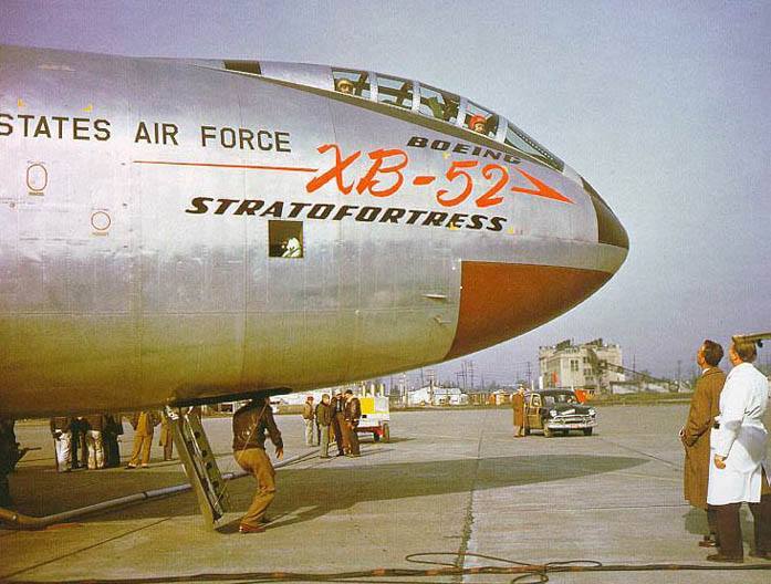
Boeing XB-52 Stratofortress 49-230 takes off for the first time, at Boeing Field, Seattle, Washington, 2 October 1952. (LIFE Magazine via Jet Pilot Overseas)
2 October 1952: The Boeing XB-52 Stratofortress prototype, 49-230, made its first flight at Boeing Field, Seattle, Washington, with test pilot Alvin M. “Tex” Johnston in command. Lieutenant Colonel Guy M. Townsend, U.S. Air Force, acted as co-pilot.
The first of two prototype long-range, high-altitude, heavy bombers, the XB-52 had been damaged during ground testing and extensive repairs were required, which delayed its initial flight. The second prototype, YB-52 49-231, made the type’s first flight nearly six months earlier, on 15 April 1952.
Alvin M. “Tex” Johnston, test pilot, after the first flight of the Boeing XB-52 Stratofortress prototype, 2 October 1952. (LIFE Magazine via Jet Pilot Overseas)
The prototype Stratofortress the largest jet aircraft built up to that time. It was 152.7 feet (46.543 meters) long with a wingspan of 185.0 feet, (56.388 meters) and 48.25 feet (14.707 meters) to the top of the vertical fin. The leading edges of the wings were swept back 36° 54′. The XB-52 had an empty weight of 155,200 pounds (70,398 kilograms) and its maximum takeoff weight was 390,000 pounds (176,901 kilograms). Fuel capacity was 27,417 gallons (103,785 liters).
Lieutenant Colonel Guy M. Townsend, U.S. Air Force. (Jet Pilot Overseas)
The XB-52 was powered by eight Pratt & Whitney YJ57-P-3 turbojet engines, with a normal power rating of 8,700 pounds static thrust at Sea Level (38.700 kilonewtons). The prototype bomber had a cruising speed of 519 miles per hour (835 kilometers per hour), and a maximum speed of 611 miles per hour (983 kilometers per hour) at 20,000 feet (6,048 meters). The planned bombing altitude was 46,500 feet (14,173 meters) and it had a service ceiling of 52,300 feet (15,941 meters). The XB-52 had an initial rate of climb of 4,550 feet per minute (23.11 meters per second) at Sea Level. Its maximum unrefueled range was 7,015 miles (11,290 kilometers).
Pilot’s cockpit, Boeing XB-52. (Boeing)Boeing XB-52 Stratofortress 49-230. (U.S. Air Force)Boeing XB-52 Stratofortress 49-230 with a North American F-86 Sabre chase plane. (U.S. Air Force)Boeing XB-52 Stratofortress 49-230. (U.S. Air Force)
In its original configuration, the XB-52 was armed with two .50-caliber machine guns in a turret in the tail, with 600 rounds of ammunition per gun, though these guns were not installed on 49-230. The XB-52 was designed to carry a single 25,200 pound (11,431 kilogram) T-28E2 Samson bomb, or other conventional or nuclear weapons.
XB-52 49-230 was used in flight testing for its entire service life. The airplane was scrapped in the mid-1960s.
744 B-52 bombers were built by Boeing at Seattle, Washington and Wichita, Kansas, with the final one, B-52H-175-BW 61-0040, rolled out 22 June 1962.
75 B-52H Stratofortresses are still in service with the United States Air Force.
Boeing XB-52, with Tex Johnston and Guy Townsend in the tandem cockpit. (Boeing)Boeing XB-52 Stratofortress 49-230 with two Pratt & Whitney J75 turbojets in single-engine nacelles on the outer pylons, circa 1959. (U.S. Air Force)
North American Aviation test pilot George S. Welch, flying the first of three XP-86 prototypes, serial number 45-59597. (North American Aviation, Inc.)
1 October 1947: After three years development in which 801,386 engineering hours and 340,594 drafting hours had been expended, the first prototype North American Aviation XP-86 (company designation NA-140), serial number 45-59597, was ready for its first flight at Muroc Dry Lake in the high desert, north of Los Angeles, California.
Completed at North American’s Inglewood plant on 8 August 1947, it was trucked to Muroc in mid-September. It was reassembled, everything was checked out, and after a few taxi tests, company test pilot George S. Welch took off for a initial familiarization flight. Chief Test Pilot Bob Chilton flew chase in an XP-82 Twin Mustang with a company photographer on board. The duration of the first flight was 1 hour, 18 minutes.
Recently completed, the first prototype XP-86, 45-59597, waits inside the North American Aviation plant at Inglewood, California, 14 August 1947. (North American Aviation, Inc.)
During this first flight, George Welch climbed to 35,000 feet (10,668 meters):
“In a little more than ten minutes he had reached 35,000 feet. Leveling out, the test pilot smiled as he watched the indicated airspeed accelerate to 320 knots. He estimated that should be 0.90 Mach number. . . Rolling into a 40 degree dive, he turned west. . . The airspeed indicator seemed to be stuck at about 350 knots. The Sabre was behaving just fine. Then at 29,000 feet, there was a little wing roll. Correcting the roll, George pushed into a steeper dive. The airspeed indicator suddenly jumped to 410 knots and continued to rise. At 25,000 feet, he pulled the Sabre into level flight and reduced power. The wing rocked again and the airspeed jumped back to 390.”
—Aces Wild: The Race for Mach 1, by Al Blackburn, Scholarly Resources Inc., Wilmington, Delaware, 1998, at Chapter 5, Pages 144–145.
George Welch was the first to report instrument readings that would be referred to as “Mach jump.” It has been argued that George Welch flew the XP-86 beyond Mach 1 during this flight, breaking the “sound barrier” two weeks before Chuck Yeager did with the Bell X-1 rocketplane. During flight testing, it was firmly established that the XP-86 could reach Mach 1.02–1.04 in a dive, so it is certainly possible that he did so on the Sabre’s first flight.
North American Aviation Model NA-140, the first XP-86 prototype, 45-59597, at Muroc AAF, 1947. (U.S. Air Force)
The XP-86 was unlike any airplane before it. It was the first airplane with a swept wing. After analyzing test data from the Messerschmitt Me 262, North American’s engineers designed a wing with a 35° degree sweepback to its leading edge. The wing tapered toward the tips, and its thickness also decreased from the root to the tip. In order to create a very strong but very thin wing, it was built with a two-layered aluminum skin, instead of ribs and spars, with each layer separated by “hat” sections. The wing sweep allowed high speed shock waves to form without stalling the entire wing.
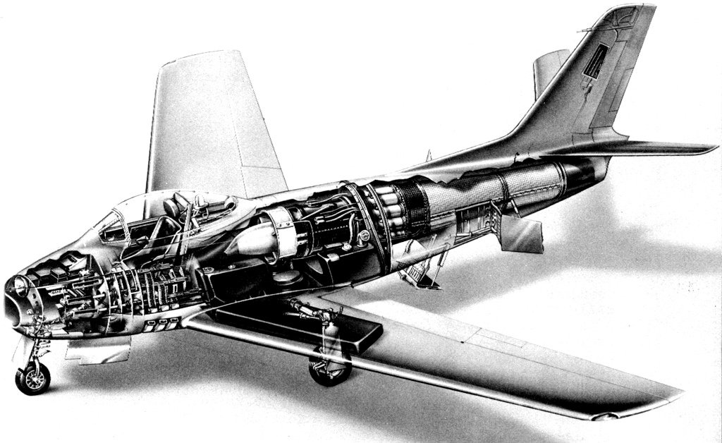
Cutaway illustration of the XP-86. The speed brake configuation was not used for production aircraft. (North American Aviation, Inc.)
The wing also incorporated leading edge “slats” which were airfoil sections that automatically extended below 290 knots, smoothing the air flow over the wing’s upper surface and creating more lift at slow speeds. Above that speed, aerodynamic forces closed the slats, decreasing drag and allowing for higher speeds. Effectively, the wing could change its shape in flight.
This photograph of the XP-86 shows the 35° wing sweep. Test pilot George S. Welch, wearing his distinctive orange helmet, in the cockpit of the prototype XP-86. (North American Aviation, Inc.)
The XP-86 prototypes were 37 feet, 6½ inches (11.443 meters) long with a wingspan of 37 feet, 1–7/16 inches (11.314 meters) and overall height of 14 feet, 9 inches (4.496 meters). The empty weight was 9,730 pounds (4,413.5 kilograms), gross weight, 13,395 pounds (6,075.9 kilograms) and maximum takeoff weight was 16,438 pounds (7,456.2 kilograms).
North American Aviation XP-86 45-59597. (Ray Wagner Collection, San Diego Air & Space Museum Archives, Catalog #: 16_002950)
The XP-86 was initially powered by a General Electric-designed, Chevrolet-built J35-C-3 turbojet which produced 4,000 pounds of thrust. This was soon changed to an Allison J35-A-5. Performance testing was conducted with the Allison engine installed. The J35 was a single-spool, axial-flow turbojet engine with an 11-stage compressor and single-stage turbine. The J35-A-5 was rated at 4,000 pounds of thrust (17.79 kilonewtons) at 7,700 r.p.m. (static thrust, Sea Level). The engine was 14 feet, 0.0 inches (4.267 meters) long, 3 feet, 4.0 inches (1.016 meters) in diameter and weighed 2,400 pounds (1,089 kilograms).
The three North American Aviation XP-86 prototypes. Front to back, 45-59598, 45-59597 and 45-59599. (National Archives and Records Administration)
The maximum speed of the XP-86 at Sea Level was 0.787 Mach (599 miles per hour, 964 kilometers per hour), 0.854 Mach (618 miles per hour, 995 kilometers per hour) at 14,000 feet (4,267 meters) and 575 miles per hour (925 kilometers per hour) at 35,000 feet (10,668 meters)—0.875 Mach.
The prototype fighter was able to take off at 125 miles per hour (201 kilometers per hour) in just 3,020 feet (920.5 meters) of runway. It could climb to 30,000 feet (9,144 meters) in 12.1 minutes and had a service ceiling of 41,300 feet (12,588 meters).
The end of XP-86 45-59597 at Frenchman Flats, 1953.
XP-86 45-59597 was expended as a target during nuclear weapons tests. On 25 May 1953, it was 1,850 feet from ground zero of Upshot Knothole Grable. The only part still intact was the engine, which was thrown 500 feet.
Upshot Knothole Grable (National Nuclear Security Administration CIC 0315864)George S. Welch, North American Aviation test pilot, wearing his orange flight helmet. An F-86 Sabre is in the background. (San Diego Air and Space Museum Photo Archives)
George Welch was born George Lewis Schwartz, in Wilmington, Delaware, 10 May 1918. His parents changed his surname to Welch, his mother’s maiden name, so that he would not be effected by the anti-German prejudice that was widespread in America following World War I. He studied mechanical engineering at Purdue, and enlisted in the Army Air Corps in 1939.
George S. Welch is best remembered as one of the heroes of Pearl Harbor. He was one of only two fighter pilots to get airborne during the Japanese surprise attack on Hawaii, 7 December 1941. Flying a Curtiss P-40B Warhawk, he shot down three Aichi D3A “Val” dive bombers and one Mitsubishi A6M2 Zero fighter. For this action, Lieutenant General H.H. “Hap” Arnold recommended the Medal of Honor, but because Lieutenant Welch had taken off without orders, an officer in his chain of command refused to endorse the nomination. He received the Distinguished Service Cross.
During World War II, George Welch flew the Bell P-39 Airacobra and Lockheed P-38 Lightning on 348 combat missions. He had 16 confirmed aerial victories over Japanese airplanes and rose to the rank of Major.
Suffering from malaria, George Welch was out of combat, and when North American Aviation approached him to test the new P-51H Mustang, General Arnold authorized his resignation. Welch test flew the P-51, FJ-1 Fury, F-86 Sabre and F-100 Super Sabre. He was killed 12 October 1954 when his F-100A Super Sabre came apart in a 7 G pull up from a Mach 1.5 dive.
An early production aircraft, North American Aviation P-86A-1-NA Sabre 47-630 (s/n 151-38457). (North American Aviation, Inc./Chicago Tribune)
After testing, the North American Aviation XP-86 was approved for production as the F-86A. It became operational in 1949. The first squadron to fly the F-86 held a naming contest and from 78 suggestions, the name “Sabre” was chosen. The F-86 Sabre was in production until 1955 at North American’s Inglewood, California, and Columbus, Ohio, plants. It was also built under license by Canadair, Ltd., Sain-Laurent, Quebec, Canada; the Commonwealth Aircraft Corporation, Port Melbourne, Victoria, Australia; and Mitsubishi Heavy Industries at Nagoya, Aichi Prefecture, Japan. A total of 9,860 Sabres were built. They served with the United States Air Force until 1970.
XP-86 45-59597 was expended in nuclear weapons tests, Operation Snapper Easy and Snapper Fox, at the Nevada Test Site, Frenchman’s Flat, Nevada, in May 1952. The second and third prototypes, 45-59598 and 45-59599, met similar fates.
Bell XP-59A Airacomet 42-108784, first flight at Muroc Dry Lake, 1 October 1942. (U.S. Air Force)
1 October 1942: At Muroc Dry Lake, in the high desert north of Los Angeles, California, Bell Aircraft Corporation’s Chief Test Pilot, Robert Morris Stanley, made the first flight of the top secret prototype turbojet-powered fighter, the Bell XP-59A Airacomet, serial number 42-108784. Weather was “C.A.V.U.” (Ceiling and Visibility Unrestricted) and wind was from the west at 20 miles per hour (9 meters per second).
Bell Aircraft Corporation Chief Test Pilot Robert M. Stanley in the cockpit of an XP-59A Airacomet. (National Museum of the United States Air Force)
In his report, Stanley wrote:
4. All take-offs were made using 15,000 r.p.m. on both engines with flaps fully up and with the airplane pulled off the ground at about 80 to 90 m.p.h. Throttle was applied promptly and acceleration during take-off appeared quite satisfactory. The run was estimated to be in the vicinity of 2,000 feet, possibly more. The first flight reached an altitude of approximately 25 feet, and landing was made using partial power without flaps. This take-off had the wind approximately 60° on the right bow and must be considered a cross-wind take-off.
5. Aileron and elevator action appear satisfactory, although the rudder force appears undesirably light causing the airplane to yaw somewhat for very light pedal pressures. Left rudder was needed for take-off due to cross wind.
—Bell Aircraft Corp. Pilot’s Report 27-923-001, at Page 1-12, by Robert M. Stanley, 1 October 1942
Bell XP-59A Airacomet 42-108784 disguised with a false propeller. (U.S. Air Force)One of the three Bell XP-59A prototypes, circa 1942. (U.S. Air Force)Bell Aircraft Corporation XP-59A Airacomet 42-108784. (U.S. Air Force photo)Bell Aircraft Corporation P-59 Airacomet with updated national insignia, after August 1943. (U.S. Air Force photo)Bell Aircraft Corporation XP-59A Airacomet 42-108784. (U.S. Air Force photo)
Stanley made three more flights that day, as high as 100 feet (30.5 meters). The following day, Army Air Corps test pilot Colonel Laurence C. Craigie conducted the “official” first flight, reaching an altitude of 10,000 feet (3,048 meters).
A Bell XP-59A Airacomet prototype in flight near Muroc Army Airfield, 1942. (U.S. Air Force)
Three XP-59A prototypes were built. The number one ship, 42-108784, was affectionately nicknamed Miss Fire, because of the initial difficulty in getting the engines to start.
The Bell XP-59A was conventional single-place airplane with retractable tricycle landing gear. It was primarily of metal construction, though the control surfaces were fabric-covered. The prototype was 38 feet, 10 inches (11.836 meters) long with a wingspan of 49 feet, 0 inches (14.935 meters) and overall height of 12 feet, 3¾ inches (3.753 meters), at rest. The leading edge of the wings were swept aft 7°. The angle of incidence was +2° with -2° twist and 2½° dihedral. The horizontal stabilizer had a span of 16 feet, 8 inches (5.080 meters). Its angle of incidence was +1½° with no dihedral. The vertical fin had 0° offset. The empty weight of the XP-59A was 7,319 pounds (3,320 kilograms) and its maximum gross weight was 10,089 pounds (4,576 kilograms).
A cutaway display of a General Electric I-A turbojet engine. The single-stage centrifugal compressor and single-stage axial-flow turbine are on a single shaft (center). One of the annular combustion chambers is sectioned at the upper left. (National Museum of the United States Air Force)
The experimental fighter was initially powered by two General Electric Type I-A centrifugal reverse-flow turbojet engines, serial numbers 170121 (left) and 170131 (right), each producing 1,250 pounds of thrust (5.561 kilonewtons) at 15,000 r.p.m. These were copies of the British Whittle W.2B engines. They were heavy, underpowered and unreliable.
Performance of the XP-59A was disappointing with a maximum speed of 350 miles per hour (563 kilometers per hour) at Sea Level and 389 miles per hour (626 kilometers per hour) at 35,160 feet (10,717 meters), significantly slower than many piston-engined fighters.
Three XP-59A prototypes and thirteen YP-59A preproduction airplanes were built. The P-59 was ordered into production and Bell Aircraft Corporation built thirty P-59A and twenty P-59B fighters. These were armed with one M4 37mm autocannon with 44 rounds of ammunition and three Browning AN-M2 .50-caliber machine guns with 200 rounds per gun.
Although a YP-59A had set an unofficial altitude record of 47,600 feet (14,508 meters), the Airacomet was so outclassed by standard production fighters that no more were ordered.
Lawrence D. Bell with his XP-59A Airacomet at Muroc Dry Lake. (Robert F. Dorr Collection)
The race for a jet engine-powered fighter had been ongoing for several years, and the United States’ XP-59A was trailing behind. The first jet airplane, the Heinkel He 178, had made its first flight in Germany three years earlier, on 27 August 1939, though it was a proof-of-concept article, not an operational military aircraft. In the United Kingdom, the Gloster E/28.39, also a proof-of-concept aircraft, though more advanced than the Heinkel, made its first flight, 15 May 1941. The world’s first operational jet fighter, the Messerschmitt Me 262, made its first flight on 18 July 1942. It was nearly two years before production Me 262s entered combat, but they were devastating against bomber formations. The Gloster Meteor, the Allies’ first jet fighter, first flew 5 March 1943, and deliveries to fighter squadrons began in July 1944. The de Havilland DH.100 Vampire made its first flight 20 September 1943, but it did not become operational until after the end of World War II.
The XP-59A flew nearly five months before its British cousin, but would not be assigned to an operational squadron, the 445th Fighter Squadron, 412th Fighter Group, until June 1945.
The first American military jet aircraft, Bell XP-59A Airacomet 42-108784, was preserved by the Army at Muroc, and the engines at Wright Field, Ohio. In 1978, these were given to the Smithsonian Institution National Air and Space Museum where the prototype was later restored and placed on display.g9
The first American jet-powered aircraft, Bell XP-59A Airacomet 42-108784 on display at the National Air and Space Museum. (NASM)