26 June 1942: The Grumman XF6F-1, Bureau of Aeronautics serial number (Bu. No.) 02981, prototype for the Navy and Marine Corps F6F Hellcat fighter, with Grumman’s Chief Engineer and Test Pilot Robert Leicester Hall flying, made a 25-minute first flight at the Grumman Aircraft Engineering Corporation plant, Bethpage, Long Island, New York.
The first Hellcat was powered by an air-cooled, supercharged, 2,603.737-cubic-inch-displacement (42.688 liters) Wright Aeronautical Division Twin Cyclone GR2600B676 (R-2600-10) two-row, 14-cylinder radial engine. This engine had a compression ratio of 6.9:1 and required 100-octane aviation gasoline. The R-2600-10 was rated at 1,500 horsepower at 2,400 r.p.m. at Sea Level, and 1,700 horsepower at 2,600 r.p.m. for takeoff. It turned a three-bladed Curtiss Electric propeller through a 0.5625:1 gear reduction. The R-2600-10 was 4 feet, 6.26 inches (1.378 meters) in diameter and 6 feet, 2.91 inches (1.903 meters) long. It weighed 2,115 pounds (959 kilograms).
Beginning with the second prototype, Bu. No. 02982, the Pratt & Whitney Double Wasp SSB2-G (R-2800-10) 18-cylinder engine became the standard powerplant. The R-2800-10 was an air-cooled, supercharged, 2,804.4-cubic-inch-displacement (45.956 liter), twin-row 18-cylinder radial engine with water injection. The engine had a compression ratio of 6.65:1 and was rated at 1,550 horsepower at 2,550 r.p.m. at 21,500 feet (6,553 meters), and 2,000 horsepower at 2,700 r.p.m. for takeoff, burning 100-octane gasoline. The engine drove a three-bladed Hamilton Standard Hydromatic constant-speed propeller with a diameter of 13 feet, 1 inch (3.988 meters) through a 2:1 gear reduction. The R-2800-10 was 4 feet, 4.50 inches (1.334 meters) in diameter, 7 feet, 4.47 inches (2.247 meters) long, and weighed 2,480 pounds (1,125 kilograms), each. The engine weighed 2,480 pounds (1,125 kilograms).
Grumman XF6F-1 Hellcat Bu. No. 02981 in flight. (Northrop Grumman)
The first prototype was quickly re-engined to the Pratt & Whitney radial and redesignated XF6F-3. Bob Hall flew it with the new engine on 30 July 1942. A few weeks later, 17 August, the Hellcat’s new engine failed and Hall crash-landed at Crane’s Farm. The airplane was moderately damaged and Hall was seriously injured.
Grumman XF6F-3 Bu. No. 02981 after crash landing in a field at Crane’s Farm, Long Island, New York, 17 August 1942. (Northrop Grumman)
The airplane was rebuilt and continued in the test program. It was eventually converted to the XF6F-4 with a two-speed turbocharged Pratt & Whitney Double Wasp 2SB-G (R-2800-27) which produced 2,000 horsepower at 2,700 r.p.m. It was armed with four 20 mm cannon.
The first prototype Hellcat was converted to the XF6F-4 configuration, seen here at NACA, Langley Field, Virginia in 1944. (NASA)
The Grumman F6F-3 Hellcat is single-place, single-engine fighter designed early in World War II to operate from the U.S. Navy’s aircraft carriers. It is a low wing monoplane monoplane of all metal construction. The wings can be folded against the sides of the fuselage for storage aboard the carriers. Landing gear is conventional, retractable, and includes an arresting hook.
The F6F-3 is 33 feet, 7 inches (10.236 meters) long with a wingspan of 42, feet 10 inches (12.842 meters) and overall height of 14 feet, 5 inches (4.394 meters) in three-point position. It has an empty weight of 9,207 pounds (4,176 kilograms) and gross weight of 12,575 pounds (5,704 kilograms).
A Grumman F6F Hellcat ready for takeoff from an Essex-class aircraft carrier, circa 1943. (U.S. Navy)
The F6F-3 Hellcat was powered by a Pratt & Whitney Double Wasp SSB2-G (R-2800-10W) engine with water injection, rated at 2,000 horsepower at 2,700 r.p.m. for takeoff, using 100/130 octane aviation gasoline. The normal power rating was 1,550 horsepower at 2,550 r.p.m. at 22,500 feet (6,858 meters). The engine drove a three-bladed Hamilton Standard Hydromatic constant-speed propeller with a diameter of 13 feet, 1 inch (3.988 meters) through a 2:1 gear reduction. The engine weighed 2,480 pounds (1,125 kilograms).
Two Grumman F6F-3 Hellcat fighters, Summer 1943. (U.S. Navy)
In clean configuration, the F6F-3 had a maximum speed of 321 miles per hour (517 kilometers per hour) at Sea Level, and 384 miles per hour (618 kilometers per hour) at 18,000 feet (5,486 meters). It could climb to 10,000 feet (3,048 meters) in 3.2 minutes, and to 20,000 feet (6,096 meters) in 7.0 minutes. The service service ceiling was 38,800 feet (11,826 meters). It had a combat radius of 335 nautical miles (386 miles/620 kilometers). The maximum ferry range was 1,540 miles (2,478 kilometers).
The Hellcat’s armament consisted of six air-cooled Browning AN-M2 .50-caliber machine guns, mounted three in each wing, with 2,400 rounds of ammunition.
The Grumman Hellcat was the most successful fighter of the Pacific war, with a kill-to-loss ratio of 19:1. It was in production from 1942 to 1945 and remained in service with the United States Navy until 1956. A total of 12,275 were built by Grumman at Bethpage. This was the largest number of any aircraft type produced by a single plant.
High humidity creates visible propeller tip vortices as this Grumman F6F-3 Hellcat prepares to takeoff from USS Yorktown (CV-10), November 1943. (U.S. Navy)
Robert Leicester Hall
Robert Leicester Hall was born at Taunton, Massachussetts, 22 August 1905. He was the son of Bicknell Hall, a mechanical engineer, and Estella Beatrice Lane Hall.
Hall attended the University of Michigan, graduating in 1927 with Bachelor of Science degree in Mechanical Engineering (B.S.M.E.).
In 1929 he went to work for the Fairchild Airplane Manufacturing Company at Farmingdale, New York. While there, Hall met his first wife, Eugenie, a secretary at the plant. They were married in 1930, and lived in a rented home on St. James Avenue, Chicopee City, Massachusetts. Their son, Robert Jr., was born 5 November 1931.
Granville Brothers Gee Bee Model Z, NR77Y, City of Springfield.
Also in 1931, Hall began working for Granville Brothers Aircraft at Springfield, Massachusetts. He designed the Gee Bee Model Z Super Sportster air racer. He left Granville Brothers in 1933 to go to work for the Stinson Aircraft Company in Dayton, Ohio. There he designed the Stinson Reliant.
A Stinson SR-8E Reliant, NACA 94, at the Langley Research Center, 5 August 1936. (NASA)
In 1936, Bob Hall became the Chief Engineer for the Grumman Aircraft Engineering Corporation, Bethpage, Long Island, New York. He designed the F4F Wildcat, F6F Hellcat, F7F Tigercat, and F8F Bearcat fighters, and the TBF Avenger torpedo bomber. As corporate vice president, he supervised the design of the F9F Panther and Cougar jet fighters.
Hall married his second wife, Rhoda C. Halvorsen, 18 January 1939, at New York City, New York.
Hall retired from Grumman in 1970. Two of his sons, Eric and Ben Hall, founded Hall Spars and Rigging of Bristol, Rhode Island.
Robert Leicester Hall died at Newport, Rhode Island, 25 February 1991, at the age of 85 years.
Grumman F6F-3 Hellcat, Bu. No. 4778, Long Island, New York, circa 1942. (Rudy Arnold Collection/NASM)
Grumman F6F-3 Hellcat Bu. No. 26108, Long Island, New York, circa 1943. (Rudy Arnold Collection/NASM)
Boeing 314 NC18603, Yankee Clipper (Harris & Ewing)
24 June 1939: The Pan American Airways System began scheduled air service from the United States to Britain. The Boeing 314 Yankee Clipper, NC18603, made the first flight from Port Washington, New York, departing at 8:21 a.m. It made intermediate stops at Shediac, New Brunswick, and Botwood, Newfoundland, where fog delayed the flying boat until 12:49 p.m., 28 June. Continuing across the Atlantic, Yankee Clipper made another stop at Foynes, Ireland, and finally arrived at Southampton at 7:25 p.m. that evening.
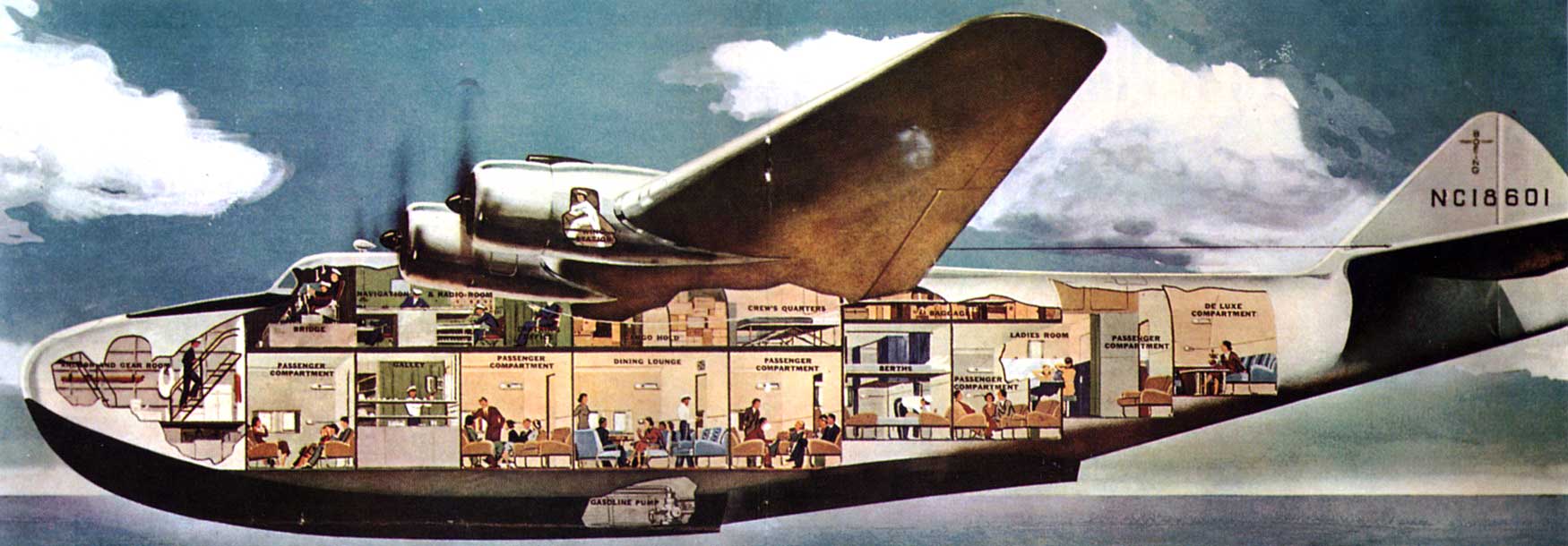
The largest airplane of the time, the Pan American Clipper flying boat could carry 77 passengers in “one class” luxury, with a ticket priced at $675—that’s in 1939 dollars. ($15,610.71 in 2025) Uniformed waiters served five and six course meals on silver service. Seats could be folded down into beds.
The flight deck of a Boeing 314. At the left, standing, is the airliner’s navigator. Beyond him are the captain (left) and co-pilot. On the right side of the cabin are the radio operator and flight engineer. (Unattributed)
The Boeing Model 314 was a large four-engine, high-wing monoplane flying boat designed and built by the Boeing Airplane Company to take off and land on water. It had a crew of 10. The wings and engine nacelles had been designed for Boeing XB-15 heavy bomber. It was 106 feet (32.309 meters) long with a wingspan of 152 feet (46.330 meters). It had a maximum take off weight of 82,500 pounds (37,421 kilograms).
The Boeing 314 was powered by four air-cooled, supercharged, 2,603.737-cubic-inch-displacement (42.668 liter) Wright Aeronautical Division Cyclone 14 GR2600A2, two-row, 14-cylinder radial engines with a compression ratio of 7.1:1. They were rated at 1,200 horsepower at 2,100 r.p.m., and 1,550 horsepower at 2,400 r.p.m. for takeoff, burning 91/96 octane gasoline. These engines (also commonly called “Twin Cyclone”) drove three-bladed Hamilton Standard Hydromatic full-feathering constant-speed propellers with a diameter of 14 feet (4.267 meters) through a 16:9 gear reduction. The GR2600A2 was 5 feet, 2.06 inches (1.576 meters) long and 4 feet, 7 inches (1.387 meters) in diameter. It weighed 1,935 pounds (878 kilograms). The engines could be serviced in flight, with access through the wings.
Pan American Airways’ Boeing 314 NC18603, Yankee Clipper.
The Boeing 314 had a maximum speed of 199 miles per hour (320 kilometers per hour), with a range of 3,685 miles (5,930 kilometers) at its normal cruising speed of 183 miles per hour (295 kilometers per hour). Its service ceiling was 13,400 feet (4,084 meters). The fuel capacity was 4,246 gallons (16,073 liters).
Boeing built six Model 314 and another six 314A flying boats for Pan American Airways and British Overseas Airways Corporation.
Yankee Clipper was destroyed 22 February 1943 at Lisbon, Portugal. A wing hit the water on landing. 24 of the 39 persons aboard were killed.
This illustration shows the interior arrangement of the Boeing 314. It was published in LIFE Magazine, circa 1937. (Boeing)
The Byrd Arctic Expedition Fokker F.VIIa/3m at Spitzbergen, Svalbard, 9 May 1927. (Ohio State University Archives)
9 May 1926: Lieutenant Commander Richard Evelyn Byrd, Jr., and Chief Aviation Pilot Floyd Bennett, United States Navy, departed Spitzbergen in the Svalbard Archipelago, Norway, on a round-trip flight to the North Pole.
Lieutenant Commander Richard E. Byrd, Jr., U.S. Navy (Library of Congress)Chief Aviation Pilot Floyd Bennett, U.S. Navy, circa April 1925 (U.S. Navy)
Their aircraft was a Fokker F.VIIa/3m three-engine, high-wing monoplane, construction number 600. The airplane was It was purchased for the Byrd Arctic Expedition by Edsel Ford, and named Josephine Ford in honor of his 3-year-old daughter, Josephine Clay Ford.
With Chief Bennett as the expedition’s pilot and Lieutenant Commander Byrd navigating, they flew approximately 840 miles (1,350 kilometers) to the Pole and returned the same day. The total duration of the flight was 15 hours, 44 minutes.
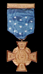
Secretary of the Navy Curtis Dwight Wilbur, Commander Richard Evelyn Byrd, Jr., President John Calvin Coolidge, Jr., Warrant Officer Floyd Bennett and Admiral Edward Walter Eberle, at the White House, 5 March 1927.Medal of Honor, U.S. Navy, 1919–1942.
For this accomplishment, Lieutenant Commander Byrd was promoted to Commander, and Chief Bennett to Warrant Officer. Both aviators were awarded the Medal of Honor by President Coolidge.
In the years since this event, there has been speculation that the airplane may not have actually reached the North Pole. Professor Gerald Newsom of Ohio State University, an astronomer who taught celestial navigation, analyzed Byrd’s handwritten notes and estimated that because of the inadequacies of the equipment then available to Byrd, Josephine Ford may have flown 21 miles (33.8 kilometers) beyond the North Pole, or fallen 78 miles (125.5 kilometers) short. Professor Newsom pointed out, though, that the fact the Byrd was able to return to Svalbard after nearly 16 hours proves that he knew how to navigate using that equipment under those conditions.
(See https://web.archive.org/web/20161216185546/http://researchnews.osu.edu/archive/byrdnorth.htm for additional information.)
Richard E. Byrd holding a Bumstead Sun Compass used for celestial navigation at very high latitudes, 1925. (Maynard Owen Williams/National Geographic Society, Image ID 612617)Fokker F.VIIa/3 Josephine Ford (David Horn Collection)Prototype Fokker F.VIIa/3m, c/n 600, at Detroit Michigan, September 1925. (Robert McMahan Collection)
Josephine Ford is the first Fokker F.VIIa/3m monoplane, c/n 600. It was built by Anton H.G. Fokker’s N.V. Koninklijke Nederlandse Vliegtuigenfabriek Fokker at Veere, Netherlands in 1925, and made its first flight at Schipol, 4 September 1925. It was demonstrated for Koninklijke Luchtvaart Maatschappij N.V. (KLM, Royal Dutch Airlines), then disassembled and shipped to the United States. 600 was flown from New York to Detroit, where it participated in the First Annual Aerial Reliability Tour, 28 September–3 October 1925, flown by Egbert P. Lott. The airplane was evaluated by the U.S. Army Air Corps at Wright Field, and was then sold to Edsel Ford.
The United States did not register aircraft prior to 1927. According to the Federal Aviation Administration’s Registry data base, FOKKER VII (TRI-MOTOR) Serial Number 600 was registered 21 June 1927 to the Ford Motor Company, Dearborn, Michigan, as NC267. The registration was cancelled 14 March 1930.
Fokker F.VII 3m Josephine Ford (Fokker Aircraft)
Sources vary as to the actual dimensions of the Fokker F.VIIa/3m. The Henry Ford, the museum which owns the airplane, gives its dimensions as 49.167 feet (14.986 meters) in length, with a wingspan of 63.5 feet (19.355 meters) and height of 12.75 feet (3.886 meters). Another source says that the airplane is 47 feet, 11 inches (14.605 meters) long with a wingspan of 63 feet, 4 inches (19.304 meters) and height of 12 feet, 8 inches (3.861 meters). Its empty weight is variously given as 4,630 pounds, 5,060 pounds or 6,724 pounds and maximum takeoff weight is 7,950 pounds, 8,800 pounds or 11,464 pounds. It has a cruise speed of 81 knots. Or 90. . . .
Josephine Ford was powered by three air-cooled 787¼-cubic-inch-displacement (12.901 liter) Wright Aeronautical Corporation Model J-4 Whirlwind nine-cylinder radial engines, rated at 215 horsepower at 1,800 r.p.m. The J-4 weighed 475 pounds. (The specific variant, J-4, J-4A, or J-4B, is not known.)
Josephine Ford is in the collection of The Henry Ford Museum, Dearborn, Michigan.
Fokker F.VIIa/3m Josephine Ford, flown by the Byrd Arctic Expedition, in the collection of The Henry Ford, Dearborn, Michigan. (The Henry Ford Museum)
Amelia Earhart with Pitcairn Autogiro Co. PCA-2 #4, NX760W, at Pitcairn Field, Warrington, Pennsylvania, 8 April 1931. (Purdue University)
8 April 1931: Amelia Earhart, flying a Pitcairn PCA-2 autogyro, reached an altitude of 18,415 feet (5,613 meters) ¹ over Warrington, Pennsylvania. The duration of the flight, her second of the day, was 1 hour, 49 minutes. She landed at 6:04 p.m.
A sealed barograph was carried aboard to record the altitude for an official record. Following the flight, the barograph was sent to the National Aeronautic Association headquarters in Washington, D.C., for certification.
An autogyro is a rotary wing aircraft that derives lift from a turning rotor system which is driven by air flow (autorotation). Unlike a helicopter, thrust is provided by an engine-driven propeller. The engine does not drive the rotor.
The Pitcairn Autogyro Company’s PCA-2 was the first autogyro certified in the United States. Operated by a single pilot, it could carry two passengers. The fuselage was constructed of welded steel tubing, covered with doped fabric and aluminum sheet.
Amelia Earhart with a Pitcairn PCA-2 autogyro.
The PCA-2 was 23 feet, 1 inch (7.036 meters) long, excluding the rotor. The low-mounted wing had a span of 30 feet, 0 inches (9.144 meters), and the horizontal stabilizer and elevators had a span of 11 feet, 0 inches. (3.353 meters). The overall height of the autogyro was 13 feet, 7 inches (4.140 meters). The PCA-2 had an empty weight of 2,233 pounds (1,013 kilograms) and gross weight of 3,000 pounds (1,361 kilograms).
The four-bladed rotor was semi-articulated with horizontal and vertical hinges to allow for blade flapping and the lead-lag effects of Coriolis force. Unlike the main rotor of a helicopter, there was no cyclic- or collective-pitch motion. The rotor system was mounted at the top of a pylon and rotated counter-clockwise, as seen from above. (The advancing blade is on the right.) The rotor had a diameter of 45 feet, 0 inches (13.716 meters). The blades were approximately 22 feet (6.7 meters) long, with a maximum chord of 1 foot, 10 inches (0.559 meters). Each blade was constructed with a tubular steel spar with mahogany/birch plywood ribs, a formed plywood leading edge and a stainless steel sheet trailing edge. They were covered with a layer of very thin plywood. A steel cable joined the blades to limit their lead-lag travel.
The aircraft was powered by an air-cooled, supercharged, 971.930-cubic-inch-displacement (15.927 liter) Wright R-975E Whirlwind 330 nine-cylinder radial engine with a compression ratio of 5.1:1. The R-975E produced a maximum 330 horsepower at 2,000 r.p.m. at Sea Level, burning 73-octane gasoline. The engine turned a two-bladed Hamilton Standard variable-pitch propeller through direct drive. The engine weighed 635 pounds (288 kilograms).
The PCA-2 had two fuel tanks with a total capacity of 52 gallons (197 liters). It also had a 6½ gallon (24.6 liter) oil tank to supply the radial engine.
The PCA-2 had a maximum speed of 120 miles per hour (193 kilometers per hour). It had a service ceiling of 15,000 feet (4,572 meters) and a range of 290 miles (467 kilometers).
Pitcairn Autogyro Co. PCA-2 NX760W at East Boston Airport, October 1930. (Courtesy of the Boston Public Library, Leslie Jones Collection.)
¹ Most sources state that Earhart set a “world altitude record” on this flight. TDiA checked with the National Aeronautic Association, which certifies aviation records in the United States. NAA has no such record in its files. Fédération Aéronautique Internationale (FAI) records show that Earhart set three world speed records in 1930, and a world distance record in 1932. She is not credited with an altitude record, or any flight record in an autogyro.
Boeing Model 307 Stratoliner NX19901 taking of at Boeing Field, Seattle, Washington. (San Diego Air & Space Museum Archives)
18 March 1939: At 12:57 p.m., Pacific Standard Time (19:47 G.M.T.), the Boeing Model S-307 Stratoliner, NX19901, took off from Boeing Field, Seattle, Washington, on Test Flight No. 19. Julius Augustus Barr was the pilot in command.
The S-307, Boeing serial number 1994, was a prototype four-engine, pressurized commercial airliner. It had first flown on 31 December 1938, with Boeing’s Chief of Flight Test, Edmund Turney (“Eddie”) Allen, as first pilot (the Pilot in Command), and Julius Barr as his copilot. Allen had flown the first eighteen flights. “The performance of aircraft NX 19901 on flights prior to Test Flight No. 19 had either met or exceeded the manufacturer’s estimates.”
Julius Barr was employed by Boeing as a test pilot, 16 November 1938. Following Flight Test No. 15, Allen approved Barr to act as first pilot on the Model 307. He first served as the pilot in command of NX19901 on 21 January 1939. This was a taxi test, with the Stratoliner never leaving the ground. Barr first flew the airplane nearly two months later, 16 March 1939, with copilot Earl Alvin Ferguson. Barr made two more flights on 17 March. Harlan Hull, Chief Pilot of Transcontinental and Western Air, Inc., flew as copilot.
At takeoff on 18 March 1939, Barr had only 2 hours, 6 minutes as pilot in command of the Boeing 307; and 17 hours, 55 minutes as second in command. He had flown as an observer aboard NX19901 for 1 hour, 52 minutes.
There were ten persons on board the Stratoliner for Test Flight No. 19. In addition to Julius Barr as P.I.C., the designated copilot was Earl Ferguson. There were two alternate copilots, Harlan Hull and Benjamin J. Pearson, an assistant sales manager for Boeing. Ralph LaVenture Cram was first aerodynamcist, assisted by John Kylstra. William C. Doyle served as oscillograph operator, and Harry T. West, Jr., was the engineering officer. These were all Boeing employees. Pieter Guillonard, technical director of Koninklijke Luchtvaart Maatschappij N.V. (KLM Royal Dutch Airlines), acted as recorder and photographer, while Albert Gillis von Baumhauer, an engineer with the Luchtvaartdienst (the Dutch Aviation Authority), acted as an assistant aerodynamicist.
Albert G. von Baumhauer
Specialized test equipment had been installed at the copilot’s position. For this reason, Von Baumhauer, rather than the designated copilot, Ferguson, was in the copilot’s seat during this test flight. (Von Baumgartner held a Dutch private pilot certificate, issued 28 November 1931. Since that time, he had flown only 116 hours, and had no experience flying multi-engine aircraft. He was not qualified to act as copilot.)
Guillonard and Von Baumhauer had recommended a series of tests to be conducted on Test Flight No. 19, including observing the airplane’s behavior following an engine cut on takeoff with no rudder input; a series of side slips and stall tests. Von Baumhauer had emphasized “complete stalls” rather than initiating recovery when stall was detected.
After takeoff, NX19901 climbed to 10,000 feet (3,048 meters) and at 140 miles per hour (225 kilometers per hour) a series of static longitudinal stability tests were performed. According to the test flight plan, side slips were to be investigated next.
Boeing 307 Stratoliner NX19901 with both propellers on right wing feathered. Note the rudder deflection. (Boeing)
At 1:12 P.M. (PST) a radio message was transmitted from NX 19901 to the Boeing Aircraft Company radio station located at Seattle, Washington, which message gave the position of the aircraft as being between Tacoma Washington and Mount Rainier at an altitude of 11,000 feet. Some two or three minutes later, while flying at a comparatively slow rate of speed in the vicinity of Alder, Washington, the aircraft stalled and began to spin in a nose down attitude. After completing two or three turns in the spin, during which power was applied, it recovered from the spin and began to dive. The aircraft partially recovered from the dive at an altitude of approximately 3,000 feet above sea level, during which recovery it began to disintegrate. Outboard sections of the left and right wings failed upward and broke entirely loose from the aircraft. Major portions of the vertical fin and portions of the rudder were carried away by wing wreckage. The outboard section of the left elevator separated from the stabilizer and both fell to the ground detached. The right horizontal tail surface, being held on by the fairing long the top surface and also by the elevator trim tab cables, remained with the fuselage. The No. 1 engine nacelle also broke loose from the aircraft and fell to the ground separately. The main body of the aircraft settled vertically and struck the ground in an almost level attitude both longitudinally and laterally at a point approximately 1,200 feet above sea level. Watches and clocks aboard the aircraft, which were broken by the force of the impact, indicated the time of the accident at approximately 1:17 p.m. (PST).
—AIR SAFETY BOARD REPORT, at Pages 34–35.
Diagram of probable flight path of NX19901 from Air Safety Board report.
All ten persons aboard were killed in the crash. The Stratoliner was destroyed. Because of the water ballast in the main fuel tanks, there was no post crash fire.
Wreckage of Boeing Model 307 Stratoliner NX19901, right rear quarter.Wreckage of Boeing Model 307 Stratoliner NX19901, right front quarter.Wreckage of Boeing Model 307 Stratoliner NX19901 near Alder, WashingtonWreckage of Boeing Model 307 Stratoliner NX19901 near Alder, Washington. (SDASM)Wreckage of Boeing Model 307 Stratoliner NX19901, left front quarter.
During the crash investigation it was found that two B-17s had previously been spun. The first,
. . . while flying with a gross load of about 42,000 pounds at an altitude of 14,000 feet, went into an inadvertent spin and made two complete turns before recovery was effected. During the pull-out from the ensuing dive, permanent distortion occurred in the structure of both wings, necessitating the installation of new wings on the aircraft.
In the second of these experiences, a similar ship was intentionally permitted to enter a spin following a complete stall. The controls were immediately reversed and the aircraft responded promptly, enabling the pilot to effect recovery after three-fourths of a turn in—
Evidence indicated that power was used in recovery from the spin in the case of NX 19901. It should be noted that in the two instances above described recovery from spin in similar aircraft was accomplished without the employment of power. In one of these cases, permanent distortion occurred in both wings.
—AIR SAFETY BOARD REPORT, at Pages 48 and 49.
Diagram of wing failure under load. (Air Safety Board Report)
PROBABLE CAUSE
Structural failure of the wings and horizontal tail surfaces due to the imposition of loads thereon in excess of those for which they were designed, the failure occurring in an abrupt pull-out from a dive following recovery from an inadvertent spin.
—AIR SAFETY BOARD REPORT, at Page 56
Crash site diagram. (Air Safety Board Report)Boeing Model 307 Stratoliner NX19901. The engine cowlings have been removed. The inboard right engine is running. The arrangement of passenger windows differs on the right and left side of the fuselage. (San Diego Air & Space Museum Archives)
The Boeing Model 307 was operated by a crew of five and could carry up to 33 passengers. It was the first pressurized airliner and, because of its complexity, it was also the first airplane to include a flight engineer as a crew member. It could maintain a cabin pressure equivalent to 12,000 feet (3,650 meters) to a pressure altitude of 19,000 feet (5,791 meters).
The Model 307 used the wings, tail surfaces, engines and landing gear of the production B-17B Flying Fortress heavy bomber. The vertical fin and rudder were of the same design as the B-17B’s, though somewhat larger. The fuselage was circular in cross section to allow for pressurization. It was 74 feet, 4 inches (22.657 meters) long with a wingspan of 107 feet, 3 inches (32.690 meters) and overall height of 20 feet, 9½ inches (6.337 meters). The wings had 4½° dihedral and 3½° angle of incidence. The empty weight was 29,900 pounds (13,562.4 kilograms) and loaded weight was 45,000 pounds (20,411.7 kilograms).
The airliner was powered by four air-cooled, geared and supercharged, 1,823.129-cubic-inch-displacement (29.875 liter) Wright Cyclone 9 GR-1820-G102 9-cylinder radial engines with a compression ratio of 6.7:1, rated at 900 horsepower at 2,200 r.p.m., and 1,100 horsepower at 2,200 r.p.m. for takeoff. These drove three-bladed Hamilton-Standard Hydromatic propellers through a 0.6875:1 gear reduction in order to match the engine’s effective power range with the propellers. The GR-1820-G102 was 4 feet, 0.12 inches (1.222 meters) long, 4 feet, 7.10 inches (1.400 meters) in diameter, and weighed 1,275 pounds (578 kilograms).
The maximum speed of the Model 307 was 241 miles per hour (388 kilometers per hour) at 6,000 feet (1,828.8 meters). Cruise speed was 215 miles per hour (346 kilometers per hour) at 10,000 feet (3,048 meters). The service ceiling was 23,300 feet (7,101.8 meters).
Boeing Model 307 Stratoliner NX19901 with all engines running. (San Diego Air & Space Museum Archives)
As a result of the crash of NX19901, production Stratoliners were fitted with a vertical fin similar to that of the B-17E Flying Fortress.
Pan American Airways’ Boeing 307 Stratoliner NC19903, photographed 18 March 1940. Note the new vertical fin. (Boeing)
Julius Augustus Barr was born at Normal, Illinois, 6 December 1905. He was the son of Oren Augustus Barr, a teacher and school superintendent, and Margaret M. Wallace Barr. He grew up in Pittsburg, Kansas. He attended the Kansas State Teachers College at Pittsburg in 1925. He was a member of the Alpha Gamma Tau (ΑΓΤ) fraternity, of which he was the treasurer.
Julius Augustus Barr
Barr enlisted in the Air Corps, United States Army, and was trained as a pilot at Brooks and Kelly Fields, San Antonio, Texas.
On 1 July 1928, Julius Barr married Miss Effie Hortense Roberson at Pittsburg, Kansas. They would have two children, Jo Anne Barr, and Gene Edward Barr.
In 1930, Barr and his family lived in Cheyenne, Wyoming. He flew as an air mail pilot, and was employed by Boeing Air Transport.
During the mid 1930s, the Barr family traveled to China, where he acted as manager of the airport at Hankow, and conducted flight training. He then flew as the personal pilot of Zhang Xueliang (also known as Chang Hseuh-Liang), (“The Young Marshal”). Zhang and another of other communist generals arrested Chiang Kai-Shek in the Xi’an Incident, December 1936. Chiang was released after two weeks, and Zhang placed under house arrest for the remainder of his life. (The others were executed.) Julius Barr then served as the personal pilot for Soong Mei-ling (“Madame Chiang”), and helped General Chang with the air defense of Shanghai during the Second Sino-Japanese War.
Barr and his family departed Hong Kong aboard S.S. Empress of Russia, which arrived at Victoria, British Columbia, Canada, 14 November 1938. He then went to work as a test pilot for Boeing two days later.
Julius Barr had flown a total of approximately 5,000 hours. Of these, 2,030 hours were in single-engine airplanes, 2,240 hours in twin-engine, and 765 hours in 3 engine.
Julius Augustus Barr was buried at the Mount Olive Cemetery, Pittsburg, Kansas.


)")