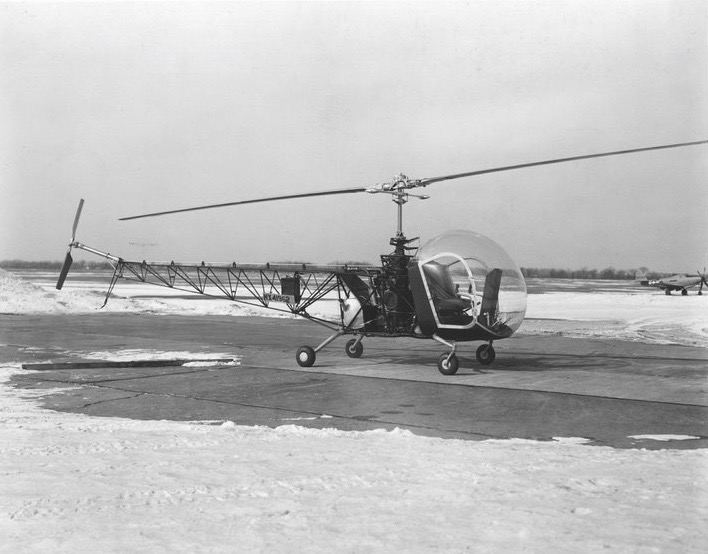
Prototype of the Bell Model 47. (Niagara Aerospace Museum)
8 December 1945: At the Bell Aircraft Corporation Wheatfield Plant, Niagara Falls, New York, the first Model 47 helicopter, NX41962, was rolled out. Designed by Arthur M. Young, the Model 47 was based on Young’s earlier Model 30. The new helicopter made its first flight on the same day.
The Civil Aviation Administration (C.A.A.), predecessor of the Federal Aviation Administration, had never certified a helicopter, so Bell worked with government officials to develop civil certification standards. The Bell 47 received the C.A.A. Type Certificate H-1 on 8 March 1946 and the first helicopter’s registration was changed to NC1H.
Bell Model 47 NX41962, Serial Number 1, at Bell’s Wheatfield Plant, early 1946. (Niagara Aerospace Museum)
The Bell 47 series was constructed of a welded tubular steel airframe with a sheet metal cockpit and a characteristic plexiglas bubble. In the original configuration, it had a four-point wheeled landing gear, but this was soon replaced with a tubular skid arrangement. It was a two-place aircraft with dual flight controls.
The first Bell Model 47 had an overall length (with rotors turning) of 39 feet, 7½ inches (12.078 meters). The main rotor diameter was 33 feet, 7 inches (10.236 meters). The length of the fuselage, from the front of the plexiglass bubble canopy to the trailing edge of the tail rotor disc, was 29 feet, 3½ inches (8.928 meters). The tail rotor had a diameter of 5 feet, 5 inches (1.676 meters). The helicopter’s height, to the top of the main rotor mast, was 9 feet, 2-7/16 inches (2.805 meters).
NC1H had an empty weight of 1,393 pounds (632 kilograms). Its gross weight was 2,100 pounds (953 kilograms).
Bell Aircraft Corp. test pilot Floyd W. Carlson demonstrates the stability of the Model 47 by taking his hands off of the flight controls during a hover. (Bell Helicopter)
The Bell 47’s main rotor is a two-bladed, under-slung, semi-rigid assembly that would be a characteristic of helicopters built by Bell for decades. The blades were constructed of laminated wood, and covered with fabric. A stabilizer bar was placed below the hub and linked to the flight controls through hydraulic dampers. This made for a very stable aircraft. The main rotor turns counter-clockwise, as seen from above. (The advancing blade is on the right.) The tail rotor is positioned on the right side of the tail boom in a tractor configuration. It rotates counter-clockwise as seen from the helicopter’s left. (The advancing blade is above the axis of rotation.)
Floyd Carlson, chief Test Pilot for the Bell Aircraft Corporation, hovers the world’s first civil-certified helicopter, NC1H, Serial Number One. (Niagara Aerospace Museum)
Power was supplied by an air-cooled, normally-aspirated, 333.991-cubic-inch-displacement (5.473 liter) Franklin Engine Company 6V4-178-B3 vertically-opposed six cylinder engine, serial number 17008, rated at 178 horsepower at 3,000 r.p.m. Power was sent through a centrifugal clutch to a transmission which turned the main rotor through a two-stage planetary gear reduction system with a ratio of 9:1. The transmission also drove the tail rotor drive shaft, and through a vee-belt/pulley system, a large fan to provide cooling air for the engine.
The new helicopter had a cruise speed of 75 miles per hour (121 kilometers per hour) and a maximum speed (VNE) of 80 miles per hour (129 kilometers per hour). NC1H had a service ceiling of 11,400 feet (3,475 meters).
The Bell 47 gained fame during the Korean War as a rescue helicopter, transferring wounded soldiers directly to Mobile Army Surgical Hospitals placed near the front lines. Here, a wounded soldier is offloaded from an H-13D-1 Sioux. (U.S. Army) The manufacturer’s data plate for Bell Model 47, Serial Number 1. (Niagara Museum of Aeronautics)
The Bell 47 was produced at the plant in New York, and later at Fort Worth, Texas. It was steadily improved and remained in production until 1974. In military service the Model 47 was designated H-13 Sioux, (Army and Air Force), HTL (Navy) and HUG (Coast Guard). The helicopter was also built under license by Agusta, Kawasaki and Westland. More than 7,000 were built worldwide and it is believed that about 10% of those remain in service.
In 2010, the type certificates for all Bell 47 models was transferred to Scott’s Helicopter Service, Le Sueur, Minnesota, which continues to manufacture parts and complete helicopters.
After certification testing and demonstrations, NC1H was one of two Bell 47s used for flight training. The first Bell 47, s/n 1, crashed at Niagara Falls Airport, 3 April 1946.
While hovering out of ground effect, a student inadvertently oversped the main rotor by decreasing collective pitch when he had intended to increase it. The main rotor hub separated and the helicopter dropped to the ground. Both the student and instructor were injured. Damage to NC1H was extensive and the helicopter was scrapped. The registration, NC1H, was reassigned to Bell 47 s/n 11.
Wreck of Bell Model 47 NC1H, s/n 1. (Niagara Aerospace Museum)
Lockheed’s Model L-188A Electra prototype, N1881, passes over Lockheed Air Terminal during its first flight, 6 December 1957. (SDASM Archives)
6 December 1957: At 10:28 a.m., Lockheed Aircraft Corporation’s Chief Engineering Test Pilot Herman Richard (“Fish”) Salmon, and co-pilot Roy Edwin Wimmer started the Number 4 engine (outboard, right wing) of the new prototype Model L-188A Electra, c/n 1001, registered N1881. Also on board were flight engineers Louis Holland and William Spreuer. In rapid succession, the flight crew started engines 1, 2, on the left wing, and 3, inboard on the right. The prototype then taxied to the eastern end of Lockheed Air Terminal’s Runway 27.¹ At 10:44, Salmon released the brakes and the Electra rapidly accelerated down the runway. It was airborne in just 1,800 feet (549 meters).
Lockheed Model L-188 Electra N1881 flying along the Southern California coastline. (SDASM Archives)
Fish Salmon took the prototype to the U.S. Navy’s restricted missile test ranges off the southern California coastline, flying between Naval Air Station Point Mugu and San Diego. During the flight, the Electra reached 400 miles per hour (644 kilometers per hour) and 14,000 feet (4,267 meters). Salmon radioed, “She controls beautifully. No sweat.”
The Electra was followed by two chase planes, a Lockheed T-33A Shooting Star, and a Super Constellation airliner. After the initial flight test, Salmon returned to LAT, landing after a flight of 1 hour, 27 minutes. The test flight was made 56 days ahead of schedule.
The prototype Lockheed Electra. N1881, crosses the threshold at Lockheed Air Terminal’s Runway 15, 6 December 1957. (SDASM Archives)
Lockheed retained N1881 as a test aircraft until April 1961, when it was sold to Friedkin Aeronautics and re-registered as N174PS. It was operated by Pacific Southwest Airlines (PSA) from May 1961 until October 1968, when it was sold to Holiday Airlines and re-registered as N974HA. The Electra was withdrawn from use and stored at Van Nuys Airport (VNY), just a few miles west of BUR, in October 1968. It is reported to have been scrapped in 1975.
Pacific Southwest Airlines Lockheed L188 Electra, N174PS (c/n 1001) at Lockheed Air Terminal, 23 September 1961. (Wikipedia).
The Lockheed Model 188A Electra is a four-engine, low-wing, commercial airliner with retractable tricycle landing gear, and powered by four turboprop engines. It was operated by a pilot, co-pilot and flight engineer, and could carry a maximum of 98 passengers. The L-188A was the first production variant. It is 104 feet, 6.5 inches (31.864 meters) long, with a wingspan of 99 feet, 0.00 inches (30.175 meters), and overall height of 32 feet, 11.6 inches (10.048 meters).
The L-188A was powered by four Allison Model 501-D13 (T56-A-1) turboprop engines. The -D13 is a single-shaft axial-flow gas turbine engine. It had a 14-stage compressor, 6-tube combustor, a 4-stage turbine. It was rated at 3,750 shaft horsepower at 13,820 r.p.m. The engines drove four-blade, square-tip Aeroproducts propellers with a diameter of 13 feet, 6 inches (4.115 meters), at 1,020 r.p.m. The -D13 is 12 feet, 1.0 inches (3.683 meters) long, 2 feet, 3.0 inches (0.686 meters) wide and 3 feet, 0.0 inches (0.914 meters) high. It weighs 1,750 pounds (794 kilograms).
Lockheed Model L-188A Electra N1881 at Lockheed Air Terminal, Burbank, California. (SDASM Archives)
Lockheed Model L-188A Electra N1881 at Lockheed Air Terminal, Burbank, California. left profile (SDASM Archives)
Lockheed Model L-188A Electra N1881 at Lockheed Air Terminal, Burbank, California. (SDASM Archives)
Lockheed Model L-188A Electra N1881 at Lockheed Air Terminal, Burbank, California. (SDASM Archives)
Critical Mach Number (Mcr) = 0.711
¹ In 1967, the name of the Lockheed Air Terminal was changed to Hollywood-Burbank Airport. After several more name changes, including Bob Hope Airport, it is once again known as Hollywood-Burbank. Its FAA identifier is BUR.
Boeing YB-17 Flying Fortress 36-149. (U.S. Air Force)
2 December 1936: The first Boeing YB-17, U.S. Army Air Corps serial number 36-149, made its first flight.
Although the prototype Boeing Model 299, X13372, had crashed at Wright Field, Ohio, 30 October 1935, the Army had ordered thirteen Y1B-17 service test aircraft, serials 36-149–36-161. Prior to the model’s first flight, this designation was changed to YB-17. (The “-1-” in the original Y1B-17 designation indicated that the service test bombers were ordered using funding other than the normal appropriations for new aircraft.)
Boeing YB-17 36-149. (U.S. Air Force)
The YB-17 had several improvements over the Model 299, which was retroactively designated XB-17. There was a long carburetor intake on top of the engine nacelles which visually distinguishes the YB-17 from the follow-on YB-17A. The main landing gear has one strut rather than the two of the Model 299. A vertical radio mast is just behind the cockpit.
Boeing YB-17 36-149. (U.S. Air Force)
The Boeing Model 299B, designated YB-17 by the Army Air Corps, was 68 feet, 4 inches (20.828 meters) long with a wingspan of 103 feet, 9⅜ inches (31.633 meters) and the overall height was 18 feet, 4 inches (5.588 meters). It had an empty weight of 24,465 pounds (11,097 kilograms), gross weight of 34,880 pounds (15,821 kilograms) and maximum takeoff weight of 42,600 pounds (19,323 kilograms).
Boeing YB-17 36-149. (U.S. Air Force)
Instead of the Pratt & Whitney engines installed on the 299, the YB-17 had four air-cooled, supercharged 1,823.129-cubic-inch-displacement (29.876 liter) Wright Aeronautical Division Cyclone 9 R-1820G5 (R-1820-39) nine-cylinder radial engines with a compression ratio of 6.45:1. They turned three-bladed Hamilton Standard constant-speed propellers through a 16:11 gear reduction drive, in order to match the engines’ effective power range with the propellers. The R-1820-39 was rated at 805 horsepower at 2,100 r.p.m., at Sea Level, and 930 horsepower at 2,200 r.p.m. for takeoff. The R-1820-39 was 45-7/16 inches (1.154 meters) long and 54¼ inches (1.378 meters) in diameter, and weighed 1,198 pounds (543.4 kilograms).
The cruise speed of the YB-17 was 217 miles per hour (349 kilometers per hour) and the maximum speed was 256 miles per hour (412 kilometers per hour) at 14,000 feet (4,267 meters). Its service ceiling was 30,600 feet (9,327 meters). The bomber’s maximum range was 3,320 miles (5,343 kilometers).
Cutaway illustration of the Boeing YB-17. (John T. Jacobsen)
The YB-17 could carry 8,000 pounds (3,629 kilograms) of bombs. Defensive armament consisted of five .30-caliber air-cooled Browning machine guns.
Boeing YB-17 36-149 nosed over on landing at Seattle, 7 December 1936. (Unattributed)
36-149 was damaged in a landing accident 7 December 1936. It was repaired and then flown to Wright Field, Dayton, Ohio, 11 January 1937. After testing at Wright Field, 36-149 was delivered to the 2nd Bombardment Group, Langley Field, Virginia. By 1938 the bomber was back at Wright Field for additional tests.
“In the summer of 1938, Bill [Captain William C. Bentley, Jr., U.S. Army Air Corps, a B-17 test pilot at Langley Field] and his aircrew flew back to Seattle to pick up an additional aircraft, YB-17 tail number 36-149 from Boeing. This aircraft was different from the original thirteen. During its assembly phase at Boeing, it was packed with additional instruments for recording purposes. Once delivered to Langley, the plane was going to be subjected to a variety of stress tests in order to determine how much damage the plane could take and still operate. During its flight to Langley, Bill arrived over the field in a thunderstorm. The strength of the storm flipped the plane upside down, a stress never envisioned by the designers for such a large aircraft, much less one loaded to capacity with measuring instrumentation and a full crew. Using his fighter pilot training, Bill flew the aircraft at its maximum altitude then performed a slow roll to bring the airplane into its proper attitude. After recovering from a harrowing spin, Bill got control of the plane and landed successfully.
“Much to the crew’s amazement, the wings were slightly bent and some rivets were missing. But the measuring instrumentation had recorded all of the stress placed on the plane. . . .”
—The Touch of Greatness: Colonel William C. Bentley, Jr., USAAC/USAF, by Stewart W. Bentley, Jr., Ph.D., AuthorHouse, Bloomington, Indiana, 2010, Chapter 2 at Page 45.
(This meant that a fourteenth YB-17, which had been built specifically as a static test article, could be completed as a Y1B-17A, 37-369.)
Boeing YB-17 at Hamilton Field, California. (U.S. Air Force)
In October 1940 36-149 was transferred to the 19th Bombardment Group at March Field, California. Finally, on 11 February 1942, it was transferred to the Air Park at Amarillo Army Air Field, a B-17 training base in Texas. It was written off 11 December 1942.
After several years of testing, the YB-17 went into production as the B-17 Flying Fortress. By the end of World War II, 12,731 B-17s had been built by Boeing, Douglas and Lockheed Vega.
Boeing YB-17 36-139 arrives at Langley Field, Virginia, 1 March 1937. (U.S. Air Force)
Boeing YB-17 36-149 at Langley Field, Virginia, 1 March 1937. (U.S. Air Force)
Boeing YB-17 36-149 at the Golden Gate International Exposition, Treasure Island, California, ca. 1939. (Stephen Fisher)
Two of the 13 Boeing YB-17 Flying Fortress (Model 299B) service test prototypes. This model can be distinguished from other early B-17s by the vertical radio mast behind the cockpit and the long carburetor intakes on the top of the engine nacelles. (Horace Bristol/LIFE Magazine)
De Havilland No. 1 at Seven Barrows, Hampshire, 1909. (BAE Systems)
History has forgotten the actual date—perhaps because he was no one of any importance at the time—but one day in the Fall or Winter of 1909, Geoffrey de Havilland, an automotive engineer, took off from Seven Barrows, Hampshire, England, in an airplane of his own design. Today, that airplane is known as the de Havilland No. 1.
De Havilland had borrowed £1,000 from his grandfather, and together with fellow engineer Francis Trounson Hearle, built an airplane.
The de Havilland No. 1 was a single-engine, single-place, three-bay biplane in a pusher configuration. It had a forward elevator (canard), and an aft-mounted rudder and adjustable horizontal stabilizer. Ailerons were mounted on the upper wing.
The structure of the airplane was built of American white wood (which proved to be a poor choice) and was braced with steel wires. The fuselage was an open girder tapered at each end. It was built of 1½″ × 1½″ (3.81 × 3.81 centimeters) longitudinals with 1¼″ × ¼″ (3.175 × 0.635 centimeter) cross braces from the engine aft. It had a cross section at the widest point of 2′4″ x 2′0″ (0.711 × 0.610 meters). The lower longitudinals were reinforced with angled steel beneath the engine
The de Havilland was 29 feet, 0 inches (8.839 meters) long with a wingspan of 36 feet, 0 inches (10.973 meters). Both wings had a chord of 6 feet, 0 inches (1.829 meters) and the vertical gap was also 6 feet, 0 inches. The wings were not staggered. The airplane weighed 850 pounds ( kilograms).
Three-view illustration of the de Havilland No. 1. (FLIGHT, 9 April 1910, Page 267)
The DH.1 was powered by a single water-cooled, normally-aspirated, 302.18 cu in (4.95 liters) de Havilland-Iris four-cylinder horizontally-opposed overhead valve engine, designed by Geoffrey de Havilland and built by the Iris Motor Co., Willesden, London. The engine produced 40 horsepower at 1,050 r.p.m., and 52 horsepower at 1,500 r.p.m. In running condition, it weighed 230 pounds (104 kilograms) including a 30 pound (14 kilogram) flywheel. The de Havilland-Iris used cast iron cylinders with a copper water jacket. The two-throw crankshaft was prone to failures after a only few hours of operation.
The engine was mounted in the airframe with its crankshaft at a right angle to the direction of flight. It drove two 7 foot, 4 inch (2.235 meter) diameter counter-rotating propellers made of aluminum. The paddle-type blades could be adjusted for pitch before flight. Tubular shafts drove through 90° bevel gears and turned the propellers at 550–600 r.p.m.
De Havilland 302 cubic inch (4.95 liter) 45-horsepower four-cylinder horizontally-opposed aircraft engine. (FLIGHT)
Cross section of de Havilland-Iris four-cylinder engine. (FLIGHT)
And it should be added that the past tense has advisably been used in the foregoing paragraph, inasmuch as the first free flight of the machine terminated in almost complete wreckage. The first time that it left the ground it did so after travelling some 40 yards on a downward slope under its own power; it then rose at a rather steep angle, which was corrected by the pilot; and almost immediately afterwards—about 35 yards from the take-off—the left main plane doubled up, causing the machine to fall heavily forward and to the left. Luckily, Mr. de Havilland himself was not hurt, but it will be observed from some of the photographs which we reproduce that the machine as such, apart from the propelling mechanism, the rudder, and the tail, was, for all practical purposes, virtually annihilated by the fall.
—FLIGHT, No. 67 (Vol. II, No. 15), 9 April 1910, Page 266, Column 1
(Flight No. 68, Vol. II, No. 16, 16 April 1910, Page 286)
The airplane’s engine was salvaged and reused in de Havilland No. 2.
The first Martin Marauder, B-26-MA 40-1361, takes off for the first time at Middle River, Maryland, 25 November 1940. (U.S. Air Force)
25 November 1940: Glenn L. Martin Company’s engineer and test pilot William Kenneth Ebel, co-pilot Ed Fenimore and flight engineer Al Malewski made the first flight of the first B-26 Marauder, Army Air Corps serial number 40-1361.
The B-26 was a twin-engine medium bomber designed with high speed as a primary objective. Production of the new airplane was considered so urgent that there were no prototypes. All aircraft were production models.
Martin B-26-MA Marauder 40-1361, right profile, with engines idling. (U.S. Air Force)
The B-26 Marauder was 58 feet, 2.5 inches (17.742 meters) long with a wingspan of 65 feet, 0 inches (19.812 meters) ¹ and overall height of 19 feet, 10.3 inches (6.053 meters). At the root, the wings’ chord was 12 feet, 10.5 inches (3.924 meters), with an angle of incidence of 3° 30′. The wing center section had no dihedral, while the the outer panels had +1° 17′. The total wing area was 602 square feet (56 square meters). The bomber had an empty weight of 21,375 pounds (9,696 kilograms) and gross weight of 32,025 pounds (14,526 kilograms).
The prototype was powered by two air-cooled, supercharged, 2,804.4-cubic-inch-displacement (45.956 liter), Pratt & Whitney R-2800-5 two-row, 18-cylinder radial engines with a compression ratio of 6.65:1. The R-2800-5 had a Normal Power rating of 1,500 horsepower at 2,400 r.p.m. to 7,500 feet (2,286 meters) and a Takeoff/Military Power rating of 1,850 horsepower at 2,600 r.p.m. to 2,700 feet (823 meters). They turned 13 foot, 6 inch (4.115 meter) diameter four-bladed, constant-speed Curtiss Electric propellers through a 2:1 gear reduction. The R-2800-5 was 6 feet, 3.72 inches (1.923 meters) long, 4 feet, 4.06 inches (1.322 meters) in diameter, and weighed 2,270 pounds (1,030 kilograms).
40-1361 had a maximum speed of 326 miles per hour (525 kilometers per hour) at 14,250 feet (4,343 meters) with the engines turning 2,400 r.p.m. Its service ceiling was 25,000 feet (7,620 meters), and the absolute ceiling was 26,200 feet (7,986 meters).
Martin B-26-MA Marauder 40-1361, the first production airplane, 25 November 1940. (U.S. Air Force)
When the B-26 entered service, it quickly gained a reputation as a dangerous airplane and was called the “widowmaker,” and also had several less polite nicknames. The airplane had relatively short wings with a small area for its size. This required that landing approaches be flown at much higher speeds than was normal practice. With one engine out, airspeed was even more critical. Some changes were made, such as a slight increase of the wingspan and the size of the vertical fin and rudder. At the same time, an emphasis was made on airspeed control during training. During World War II, the Marauder had the lowest rate of combat losses of any American bomber.
Prototype Martin B-26 40-1361 taxiing. (U.S. Air Force)
201 B-26s were built before production switched to the B-26A. Glenn L. Martin Co. produced 5,288 Marauders between 1941 and 1945, with manufacturing taking place at Middle River, Maryland, and Omaha, Nebraska. The Marauder served in the Pacific, Mediterranean and European combat areas, with both the United States and several Allied nations. When it was removed from service at the end of World War II, the “B-26” designation was reassigned to the Douglas A-26 Invader, a twin-engine light bomber.
The first Martin Marauder, B-26-MA 40-1361, was written off after a belly landing at Patterson Field, Ohio, 8 August 1941.
Martin B-26 40-1361 with engines turning, 28 November 1940. (U.S. Air Force)
William Kenneth Ebel was born at Orangeville, Illinois, 2 January 1899. He was the first of two sons of Willam Henry Ebel, a farmer, and Nora Agnes Rubendall Ebel.
Ken Ebel attended Heidelberg College at Tiffin, Ohio. While at Heidelberg, on 1 October 1918, he enlisted as a private in the Student Army Training Corps (S.A.T.C.). With World War I coming to an end in November, Private Ebel was discharged 20 December 1918. Ebel graduated from Heidelberg in 1921 with a bachelor of arts degree.
Ebel returned to military service, enlisting as a private in the 104th Squadron (Observation), Maryland National Guard, based at Baltimore, Maryland.
Ebel continued his college education at the Case School of Applied Science in Cleveland, Ohio. In 1923, he earned a bachelor of science degree in mechanical engineering (B.S.M.E.)
Ken Ebel, 104th Observation Squadron.
On 11 September 1923, Private Ebel was appointed an aviation cadet, graduating from primary flying school on 3 June 1924. He received a commission as a 2nd lieutenant, Officers Reserve Corps (O.R.C.), United States Army, on 12 June 1925.
Continuing to serve as a reserve officer, in 1926 Ebel went to work as an engineer for the Glenn L. Martin Company, then located in Cleveland, Ohio. As a test pilot and engineer, Ebel flew the Martin M-130 four-engine flying boat.
2nd Lieutenant Ebel,still with the 104th Squadron, Maryland National Guard, was promoted to the rank of 1st lieutenant on 21 December 1928. The U.S. Army advanced his rank to 1st lieutenant, Air Corps, 15 February 1929.
On 21 October 1929, William K. Ebel married Miss Florence E. Sherck at Seneca, Ohio. They would have two children, William Kenneth, Jr., and Lydia Lynn Ebel.
While testing a Martin BM-2 dive bomber, on 11 August 1932, W.K. Ebel “leaped to safety in a parachute Friday when a bombing plane he was testing failed to come out of a spin and crashed at Dahlgren, Virginia. The plane was going through its final tests before being delivered to the navy. It was wrecked in the crash.” Ebel became Member No. 495 of The Caterpillar Club.
Martin M-130 NX14714 during engine testing. (Glenn L. Martin Co.)
On Thursday, 20 December 1934, Chief Pilot Ken Ebel took the new four-engine Martin M-130 flying boat, Pan American Airways System’s Hawaii Clipper, for its first flight from Middle River, Maryland. He also made the first flight of the M-156 “Russian Clipper” in 1935.
Ebel was promoted to captain, Air Corps, on 5 January 1935. On 21 August, he delivered the new Martin Model 146 “mystery bomber” to Wright Field for evaluation by the Bombardment Board.
The Martin Model 146 medium bomber prototype at Wright Field for evaluation, 1935. (Ray Wagner Collection, San Diego Air & Space Museum Archives)
In 1942, Ken Ebel earned a doctorate (Ph.D.) in engineering from the Case School of Applied Science.
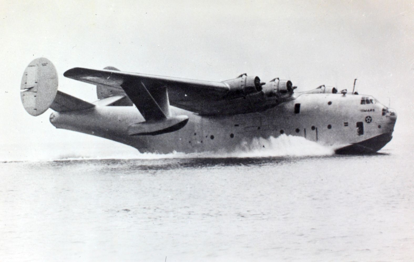
On 3 July 1942, Ken Ebel took the Martin XPB2M-1 Mars flying boat prototype for its first flight.
Martin XPB2M-1 Mars taxi test, 1942. (Charles M. Daniels Collection, San Diego Air & Space Museum Archives)
In 1948, Ken Ebel became director of the Airplane Division of the Curtiss-Wright Corporation in Columbus, Ohio. Soon after, Curtiss-Wright sold its airplane division to North American Aviation. In 1950, the U.S. Navy’s primary submarine builder, the Electric Boat Company, appointed Ebel as Vice Pressident of Engineering for its Canadair Ltd., aircraft manufacturing subsidiary in Montreal, Quebec, Canada. (In 1952, after acquiring Convair, the corporation reorganized as General Dynamics.
William K. Ebel
Ebel returned to the United States in 1961 and served as a consultant for General Dynamics in Washington, D.C. Ebel retired in 1963, purchasing teh Mount Pleasant Orchards near Baltimore.
Mrs. Ebel died in 1968. He later married Helene H. Topping.
William Kenneth Ebel, Ph.D., died at the Greater Baltimore Medical Center, 12 July 1972.
¹ The wing span was increased to 71 feet, 0 inches (21.641 meters) with the B-26B-10-MA.


")