Daily Archives: July 22, 2023

Christopher Columbus Kraft, Jr. (28 February 1924–22 July 2019)

“Flight.” Chris Kraft as Flight Director during the Mercury Program. (NASA)

From NASA:

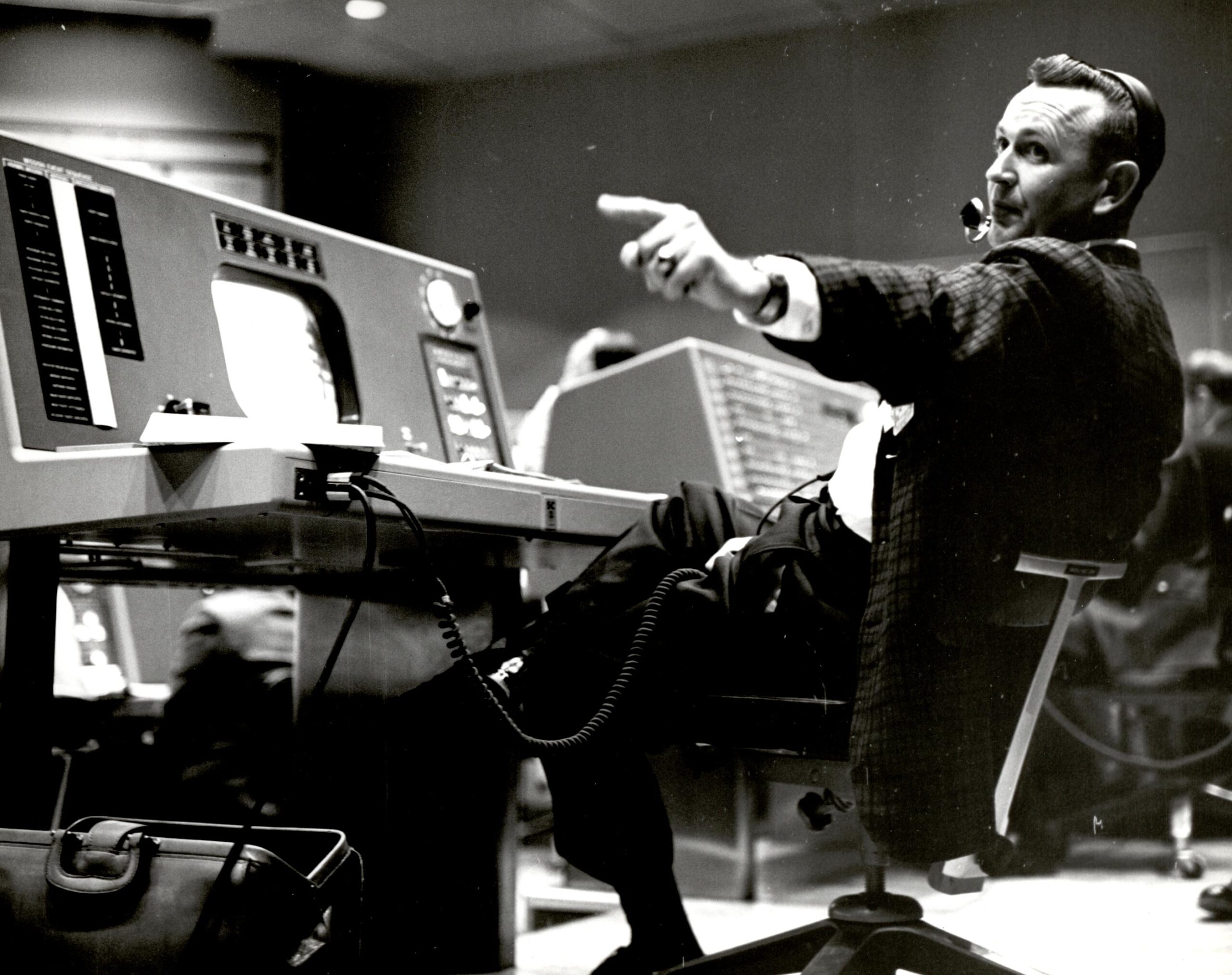
Christopher C. Kraft, Jr., who died July 22, 2019, created the concept of NASA’s Mission Control and developed its organization, operational procedures and culture, then made it a critical element of the success of the nation’s human spaceflight programs.

“America has truly lost a national treasure today with the passing of one of NASA’s earliest pioneers – flight director Chris Kraft,” NASA Administrator Jim Bridenstine said in a statement. “We send our deepest condolences to the Kraft family.

“Chris was one of the core team members that helped our nation put humans in space and on the Moon, and his legacy is immeasurable. Chris’ engineering talents were put to work for our nation at the National Advisory Committee for Aeronautics, before NASA even existed, but it was his legendary work to establish mission control as we know it for the earliest crewed space flights that perhaps most strongly advanced our journey of discovery. From that home base, America’s achievements in space were heard across the globe, and our astronauts in space were anchored to home even as they accomplished unprecedented feats.”

Kraft — whose full name was Christopher Columbus Kraft — joined the NASA Space Task Group in November 1958 as NASA’s first flight director, with responsibilities that immersed him in mission procedures and challenging operational issues. He personally invented the mission planning and control processes required for crewed space missions, in areas as diverse as go/no-go decisions, space-to-ground communications, space tracking, real-time problem solving and crew recovery.

During the Apollo program, Kraft became the Director of Flight Operations at MSC, responsible for overall human spaceflight mission planning, training and execution. His leadership in this critical area continued through the Apollo 12 mission in 1969, at which time he became deputy director of the Center. He served as the center director from January 1972 until his retirement in August 1982, playing a vital role in the success of the final Apollo missions, the Skylab crewed space station, the Apollo-Soyuz Test Project and the first flights of the space shuttle.

Kraft was born Feb. 28, 1924 in Phoebus, Virginia, now a part of Hampton, Va. There he attended high school and developed strong interests in non-aeronautical topics such as baseball, and drum and bugle corps. Unlike many of his aerospace peers later in his career, he wasn’t interested in airplanes. After high school, he wanted to attend college, but didn’t know where or what he should study. He chose Virginia Polytechnic Institute (VPI, now Virginia Tech) and enrolled in mechanical engineering in 1941. He credits his experiences in the military Corps of Cadets at the institute for the foundation of his leadership training that would later characterize his personality in his NASA career.

By 1942, the VPI campus was being depleted of students because of the war effort, and Kraft patriotically decided to join the Navy as an aviation cadet. Unfortunately, his right hand had been severely burned when he was three years old, and he was declared unfit for military service. Ironically, his old hand injuries did not hamper his athletic prowess — he played catcher on the VPI baseball team. A professor in the engineering department was an enthusiastic airplane devotee and passed his interest on to young Kraft. An elective course in basic aerodynamics inspired him to major in aeronautical engineering. In 1944, he graduated with one of the first degrees in that field awarded by the Institute.

Kraft was familiar with the work of the federal National Advisory Commitee on Aeronautics — NASA’s predecessor agency — at Langley, which was located only about 7 miles from his home. However, he felt that Langley was too close to home, and accepted a job offer from Chance Vought in Connecticut — with a back-up offer from the NACA also in hand. After experiencing first-day bureaucratic frustration at Vought, he opted to accept his back-up offer. So, in January 1945, he returned to Virginia to join the staff of the Langley Memorial Aeronautical Laboratory. Kraft was assigned to the Flight Research Division under the leadership of Robert Gilruth and Hewitt Phillips, men he held in awe. He contributed to many critical programs that had been conceived by Gilruth, including evaluations of the flying qualities of aircraft, and free-fall model tests to measure transonic and supersonic aerodynamics. He served as project engineer on flying-qualities investigations of the P-51H, an advanced version of the famous Mustang. He also conducted analytical work on gust alleviation, and directed a pioneering study of potentially dangerous wake turbulence caused by trailing vortices.

With the advent of the jet age of the 1950s, he was assigned as project engineer on flight tests of the Navy’s high-priority Vought F8U Crusader, which was exhibiting numerous birthing problems in its earliest versions. The problems uncovered by Langley flight tests included unacceptable g-force control behavior during maneuvers, which was determined to result from unintentional pivoting of the unique movable wing used by the configuration. Working with Langley test pilot Jack Reeder, Kraft identified the structural source of the problem, and took on the unpleasant job of telling the Navy that its new first-line aircraft was potentially dangerous. His warnings were heeded by Navy management, resulting in grounding of the F8U fleet, much to the chagrin of many operators of the new aircraft. He then encountered one of the most contentious members of the Navy’s Bureau of Aeronautics, who questioned the Langley results and doubted the conclusions drawn by the NACA. That Marine Major was named John Glenn. Following a detailed examination of the Langley study results with Kraft and Reeder, and interviews with Navy pilots who flew the aircraft, Glenn was convinced and became a believer. The F8U was subsequently redesigned, as recommended by Kraft and his associates at Langley, and served the nation as an outstanding fighter during the Vietnam War.

Since his retirement from NASA, Kraft has consulted for numerous companies including IBM and Rockwell International, served as a Director-at-Large of the Houston Chamber of Commerce, and as a member of the Board of Visitors at Virginia Tech. In 2001, he published an autobiography entitled “Flight: My Life in Mission Control.” His book is a detailed discussion of his life through the end of the Apollo program, and was a New York Times bestseller.

He has received numerous awards and honors for his work. These include the NASA Outstanding Leadership Medal; four NASA Distinguished Service Medals; the Distinguished Alumnus Citation from Virginia Tech, in 1965; the Distinguished Citizen Award, given by the City of Hampton, Virginia, in 1966; the John J. Montgomery Award, in 1963; the Goddard Memorial Trophy, awarded by the National Space Club, in 1979; and the John F. Kennedy Astronautics Award for 1996. In 1999, he was presented the Rotary National Award for Space Achievement for which he was cited as “A driving force in the U.S. human space-flight program from its beginnings to the Space Shuttle era, a man whose accomplishments have become legendary.”

In 2006, NASA honored Christopher C. Kraft, Jr., for his key involvement in America’s space programs with the Ambassador of Exploration Award, given to astronauts and other key individuals who participated in the Mercury, Gemini, and Apollo space programs, for realizing America’s vision of space exploration from 1961 to 1972.

On April 4, 2011, NASA named its Building 30 Mission Control Center at the Johnson Space Center in his honor, in recognition of his service to the nation and its space programs. The Christopher C. Kraft, Jr., Mission Control Center has now operated for 50 years in support of space missions. At the naming ceremony, Flight Director Glynn Lunney commented “The Control Center today…is a reflection of Chris Kraft.”

Chris Kraft married his high school sweetheart, Betty Anne Turnbull, in 1950. They have a son and a daughter, Gordon and Kristi-Anne.

Last Updated: July 23, 2019
Editor: Brian Dunbar
TDiA recommends: FLIGHT: My Life in Mission Control, by Christopher C. Kraft and James L. Schefter, Dutton, New York, 2001.

5 August 1982–22 July 1983

Dick Smith’s Bell 206B-3 JetRanger III, VH-DIK, at Ball’s Pyramid, the world’s tallest sea stack, 12 miles southeast of Lord Howe Island in the South Pacific Ocean. (Dick Smith Collection)

22 July 1983: Richard Harold (“Dick”) Smith landed his Bell JetRanger III helicopter, VH-DIK, at the Bell Helicopter Hurst Heliport (0TE2), in Hurst, Texas, United States of America. He had completed the first solo around-the-world flight by helicopter.

Dick Smith, with his wife, “Pip,” being interviewed at Hurst, Texas. His Bell 206B-3 JetRanger III, VH-DIK, is in the background. (Bell Helicopter TEXTRON)

352 days earlier, 5 August 1982, Dick Smith had departed from Hurst on an eastbound circumnavigation. He had purchased the helicopter specifically to make this flight, and named it Australian Explorer. The aircraft, as standard production Bell Model 206B-3, serial number 3653, had been built at the Bell Helicopter TEXTRON plant in Hurst. It was registered  VH-DIK by the Australia Department of Aviation, 2 June 1982.

The JetRanger was equipped with a Collins LRN 70 VLF/Omega navigation system, and a Collins autopilot. A larger fuel tank was installed.

Smith’s journey was made in three major segments:

Leg 1: Hurst, Texas, U.S.A., to London, England, from 5 August to 19 August 1982

Leg 2: London, England, to Sydney, New South Wales, Australia, 13 September to 3 October 1982

Leg 3: Sydney, N.S.W., Australia, to Hurst, TX, U.S.A., 25 May to 22 July  1983

The total distance flown was reported in FLIGHT as 32,258 miles (51,914 kilometers). The total flight time was over 260 hours.

Smith’s circumnavigation had also included the first solo flight by helicopter across the Atlantic Ocean. During the journey, he set five separate Fédération Aéronautique Internationale (FAI) world records for Speed Over a Recognized Course. ¹

Dick Smith’s Bell Model 206B JetRanger III, VH-DIK (c/n 3653), Australian Explorer. (Museum of Applied Arts & Sciences)

The Bell JetRanger is a 5-place, single-engine light civil helicopter developed from Bell Helicopter’s unsuccessful OH-4 entrant for the U.S. Army’s Light Observation Helicopter (LOH, or “loach”) contract. It is flown by a single pilot in the right front seat. Dual flight controls can be installed for a second pilot. The helicopter was certified for VFR flight, but could be modified for instrument flight.

The JetRanger is 38 feet, 9.5 inches (11.824 meters) long, overall. On standard skid landing gear the overall height is 9 feet, 4 inches (2.845 meters). The Bell 206A has an empty weight of approximately 1,700 pounds (771 kilograms), depending on installed equipment. The maximum gross weight is 3,200 pounds (1,451.5 kilograms). With an external load suspended from the cargo hook, the maximum gross weight is increased to 3,350 pounds (1,519.5 kilograms).

Three view drawing of the Bell Model 206A/B JetRanger with dimensions. (Bell Helicopter TEXTRON)

The two-bladed main rotor is semi-rigid and under-slung, a common feature of Bell’s main rotor design. It has a diameter of 33 feet, 4.0 inches (10.160 meters) and turns counter-clockwise (seen from above) at 394 r.p.m. (100% NR). (The advancing blade is on the helicopter’s right side.) The rotor blade has a chord of 1 foot, 1.0 inches (0.330 meter) and 10° negative twist. The airfoil is symmetrical. The cyclic and collective pitch controls are hydraulically-boosted.

The two-bladed tail rotor assembly is also semi-rigid and is positioned on the left side of the tail boom in a pusher configuration. It turns at 2,550 r.p.m., clockwise, as seen from the helicopter’s left. (The advancing blade is below the axis of rotation.) The tail rotor diameter is 5 feet, 6.0 inches (1.676 meters).

The turboshaft engine is mounted above the roof of the fuselage, to the rear of the main transmission. Output shafts lead forward to the transmission and aft to the tail rotor 90° gear box. The transmission and rotor mast are mounted tilting slightly forward and to the left. This assists in the helicopter’s lift off to a hover, helps to offset its translating tendency, and keeps the passenger cabin in a near-level attitude during cruise flight.

A vertical fin is attached at the aft end of the tail boom. The fin is offset 4° to the right to unload the tail rotor in cruise flight. Fixed horizontal stabilizers with an inverted asymmetric airfoil are attached to the tail boom. In cruise flight, these provide a downward force that keeps the passenger cabin in a near-level attitude.

The 206A was powered by an Allison 250-C18 turboshaft engine (T63-A-700) which produced a maximum of 317 shaft horsepower at 104% N1, 53,164 r.pm. The improved Model 206B JetRanger and 206B-2 JetRanger II used a 370 horsepower 250–C20 engine, and the Model 206B-3 JetRanger III had 250-C20B, -C20J or -C20R engines installed, rated at 420 shaft horsepower at 105% N1, (53,519 r.p.m.). Many 206As were upgraded to 206Bs and they are sometimes referred to as a “206A/B.” The Allison 250-C20B has a 7-stage compressor section with 6-stage axial-flow stages, and 1 centrifugal-flow stage. The 4-stage axial-flow turbine has a 2-stage gas producer (N1) and 2-stage power turbine (N2). These were very light weight engines, ranging from just 141 to 173 pounds (64.0 to 78.5 kilograms).

The helicopter’s main transmission is limited to a maximum input of 317 shaft horsepower (100% Torque, 5-minute limit). The engine’s accessory gear unit reduces the output shaft speed to 6,016 r.p.m. N2, which is further reduced by the transmission’s planetary gears, and the tail rotor 90° gear box.

The JetRanger has a maximum speed, VNE, of 150 miles per hour (241 kilometers per hour) up to 3,000 feet (914 meters). Its best rate of climb, VY, is at 60 miles per hour (97 kilometers per hour) and best speed in autorotation (minimum rate of descent and maximum distance) is at 80 miles per hour (129 kilometers per hour), resulting in a glide ratio of about 4:1. The service ceiling is 13,500 feet (4,145 meters) with the helicopter’s gross weight above 3,000 pounds (1,361 kilograms), and 20,000 feet (6,096 meters) when below 3,000 pounds. The helicopter has a maximum range of 430 miles (692 kilometers).

Richard Harold (“Dick”) Smith, AO, 1999. (Rob Tuckwell/National Portrait Gallery 2012.216)

¹ FAI Record File Numbers 2286, 2287, 2288, 10033 and 10272

© 2018, Bryan R. Swopes

22 July 1944

22 July 1944: During an air attack on a Japanese seaplane base and barge landing at Kokas, Enga, Dutch New Guinea, a Douglas A-20G-25-DO Havoc light attack bomber, serial number 43-9432, was hit by anti-aircraft gunfire and crashed into the sea. The pilot, 1st Lieutenant James L. Knarr, on his 70th combat mission, and gunner Staff Sergeant Charles G. Reichley, on his 46th, were killed. The A-20, named Bevo, had been assigned to the 387th Bombardment Squadron, 312th Bombardment Group, based at the Hollandia Airfield Complex.

1. Bevo, a Douglas A-20G Havoc, at the upper right, has been hit by anti-aircraft gunfire and banks right. (U.S. Air Force)
1. Bevo, a Douglas A-20G Havoc, at the upper right, has been hit by anti-aircraft gunfire and banks right, trailing smoke from the open bomb bay. (U.S. Air Force, 53686 A.C.)
2. With the smoke increasing, the A-20 continues to roll right wing down and quickly loses altitude. (U.S. Air Force)
2. With the smoke increasing, the A-20 continues to roll right and quickly loses altitude. (U.S. Air Force, A-53686 A.C.)
3. The attack bomber hits the water and begins to disintegrate. (U.S. Air Force)
3. The attack bomber hits the water and begins to disintegrate. (U.S. Air Force, B-53686 A.C.)
4. Wreckage explodes across the surface of the water. (U.S. Air Force)
4. Wreckage explodes across the surface of Sekar Bay. (U.S. Air Force, C-53686 A.C.)

The Douglas A-20G Havoc was a twin-engine light bomber developed from an earlier export aircraft produced for France and Britain. (In British service, it was known as the Boston. 7,348 A-20s were built at Douglas Aircraft Company plants in Long Beach, El Segundo and Santa Monica, California, from 1939 to 1945. All 2,850 of the A-20G variant were built at Santa Monica from 1943 to 1945.

The A-20G was 48 feet (14.630 meters) long with a wingspan of 61 feet, 4 inches (18.694 meters) and overall height of 17 feet, 7 inches (5.359 meters). It had an empty weight of 17,200 pounds (7,802 kilograms) and maximum takeoff weight of 30,000 pounds (13,608 kilograms).

The A-20G was powered by two air-cooled, supercharged, 2,603.7-cubic-inch-displacement (42.688 liters) Wright Aeronautical Corporation GR2600A5B-0 Cyclone 14 (R-2600-23) two-row, fourteen-cylinder radial engines, each rated at 1,350 horsepower at 2,300 r.p.m., and 1,600 horsepower 2,400 r.p.m., for takeoff. The engines (also commonly called the “Twin Cyclone”) turned three-bladed Hamilton Standard Hydromatic constant-speed propellers with a diameter of 12 feet, 7 inches (3.835 meters) through a 0.5625:1 gear reduction. The R-2600-23 was 4 feet, 10.32 inches (1.481 meters) long, 4 feet, 7.1 inches (1.400 meters) in diameter, and weighed 2,056 pounds (933 kilograms).

The A-20G had a cruise speed of 230 miles per hour (370 kilometers per hour) and maximum speed of 339 miles per hour (546 kilometers per hour) at 12,400 feet (3,780 meters). The service ceiling was 25,800 feet (7,864 meters). Range with a 2,000 pound (907 kilogram) bomb load was 1,025 miles (1,650 kilometers).

The A-20G Havoc was armed with six forward-firing .50-caliber Browning machine guns with 350 rounds of ammunition per gun, a power turret with another two .50-caliber guns and 400 rounds per gun, and a ninth .50 mounted in a ventral tunnel with 400 rounds. The bomber could carry 2,000 pounds (907 kilograms) of bombs in the internal bomb bay and a 500 pounder (227 kilograms) on a hardpoint under each wing.

This Douglas A-20G-45-DO Havoc, 43-22200, at the National Museum of teh United States Air Force, is marked as A-20G-40-DO 43-21475 of the 389th Bombardment Squadron, 312th Bombardment Group. (U.S. Air Force)
This Douglas A-20G-45-DO Havoc, 43-22200, at the National Museum of the United States Air Force, is marked as A-20G-40-DO 43-21475 of the 389th Bombardment Squadron, 312th Bombardment Group. (U.S. Air Force)

© 2016, Bryan R. Swopes

22 July 1943

22 July 1943: A Royal Air Force official photographer visited No. 617 Squadron, The Dambusters, at their base at RAF Scampton, Lincolnshire, England. These photographic images are part of the Ministry of Information Second World War Colour Transparency Collection.

Wing Commander Guy Gibson with members of his crew. Left to right: Wing Commander Guy Gibson, VC, DSO and Bar, DFC and Bar; Pilot Officer P M Spafford, bomb aimer; Flight Lieutenant R E G Hutchinson, wireless operator; Pilot Officer G A Deering and Flying Officer H T Taerum, gunners. (Imperial War Museum TR 1127)
Wing Commander Guy Gibson with members of his crew. Left to right: Wing Commander Guy Gibson, VC, DSO and Bar, DFC and Bar; Pilot Officer P M Spafford, bomb aimer; Flight Lieutenant R E G Hutchinson, wireless operator; Pilot Officer G A Deering and Flying Officer H T Taerum, gunners. (Imperial War Museum TR 1127) 
Wing Commander Guy Gibson sitting in a poppy field reading a book. (Imperial War Museum TR 1125)
The crew of Lancaster ED285/`AJ-T' sitting on the grass, posed under stormy clouds. Left to right: Sergeant G Johnson; Pilot Officer D A MacLean, navigator; Flight Lieutenant J C McCarthy, pilot; Sergeant L Eaton, gunner. In the rear are Sergeant R Batson, gunner; and Sergeant W G Ratcliffe, engineer. Flight Lieutenant Joe McCarthy (fourth from left) and his crew of No. 617 Squadron (The Dambusters) at RAF Scampton, 22 July 1943.
The crew of Lancaster ED285/`AJ-T’ sitting on the grass, posed under stormy clouds. Left to right: Sergeant G Johnson; Pilot Officer D A MacLean, navigator; Flight Lieutenant J C McCarthy, pilot; Sergeant L Eaton, wireless operator. In the rear are Sergeant R Batson, gunner; and Sergeant W G Ratcliffe, engineer.
Flight Lieutenant Joe McCarthy (fourth from left) and his crew of No. 617 Squadron (The Dambusters) at RAF Scampton, 22 July 1943. (Imperial War Museum TR 1128)
Flight Lieutenant Dave Shannon, pilot of ED929/`AJ-L' on the dams raid, with Flight Lieutenant R D Trevor-Roper, who flew as Gibson's rear gunner on the dam's raid; and Squadron Leader G W Holden. (Imperial War Museum TR 1129)
Flight Lieutenant Dave Shannon, pilot of ED929/`AJ-L’ on the dams raid, with Flight Lieutenant R D Trevor-Roper, who flew as Gibson’s rear gunner on the dam’s raid; and Squadron Leader G W Holden. (Imperial War Museum TR 1129)
Flight Lieutenant Harold Sydney Wilson and crew. They did not fly on the Dams raid owing to illness. Left to right: Flight Sergeant Trevor H Payne, front gunner; Pilot Officer Thomas W Johnson, flight engineer; Sergeant Eric Hornby, rear gunner; Sergeant Lloyd G Mieyette, wireless operator; Pilot Officer George H Coles, bomb-aimer; Flying Officer James A Rodger, navigator; and Flight Lieutenant Harold S Wilson. All were killed when their Lancaster was shot down on the night of 15 /16 September 1943 during the raid on the Dortmund-Ems Canal. (Imperial War Museum TR 1126)
Wing Commander Guy Gibson at his desk with Squadron Leader D J H 'Dave' Maltby, one of his flight commanders. (Imperial War museum TR 1122)
Wing Commander Guy Gibson at his desk with Squadron Leader D J H ‘Dave’ Maltby, one of his flight commanders. (Imperial War Museum TR 1122)

© 2016, Bryan R. Swopes

22 July 1933

Wiley Hardeman Post, 1898–1935. (Underwood & Underwood)

22 July 1933: At 11:50½ p.m., Wiley Hardeman Post and his Lockheed Model 5C Vega, NR105W, The Winnie Mae of Oklahoma, landed at Floyd Bennett Field, Long Island, New York.

Post had departed from there on 15 July and in 7 days, 18 hours, 49½ minutes, he flew 15,596 miles (25,099.3 kilometers), circling the Northern Hemisphere. He made 11 stops for fuel and rest, and had one minor accident which required repairs to the airplane. (Note the Standard propeller clearly visible in the photograph below.)

In 1931, he had flown approximately the same route, with a navigator, Harold Gatty, aboard. For this flight Post was by himself.

This was the first solo around-the-world flight. Wiley Post was the first pilot to have flown around the world twice.

Wiley Post climbs out of the cockpit of his Lockheed Vega monoplane, Winnie Mae, after completing the first solo flight around the world at Floyd Bennet Field, Long Island, N.Y., midnight, July 22, 1933. Wiley set a new record with the distance of 15,596 miles, 25,099 kilometer, in 7 days, 18 hours, 49 minutes. (AP Photo)
“Wiley Post climbs out of the cockpit of his Lockheed Vega monoplane, Winnie Mae, after completing the first solo flight around the world at Floyd Bennett Field, Long Island, N.Y., midnight, July 22, 1933. Wiley set a new record with the distance of 15,596 miles, 25,099 kilometer, in 7 days, 18 hours, 49 minutes.” (AP Photo)

The Vega was a single-engine, high-wing monoplane was designed by John Knudsen (“Jack”) Northrop and Gerrard Vultee. It was a very state-of-the-art aircraft for its time. It used a streamlined monocoque fuselage made of spiral strips of vertical grain spruce pressed into concrete molds and held together with glue. The wing and tail surfaces were fully cantilevered, requiring no bracing wires or struts to support them.

The techniques used to build the Vega were very influential in aircraft design. It also began Lockheed’s tradition of naming its airplanes after stars and other astronomical objects.

The Winnie Mae was built by Lockheed Aircraft Company at Burbank, California in 1930 as a Model 5B Vega, serial number 122. It was purchased by an Oklahoma oil driller, Florence C. (“F.C.”) Hall, on 21 June 1930, and named for his daughter, Winnie Mae Hall, The Winnie Mae of Oklahoma. The new airplane was painted white with purple trim. In 1932, NC105W was modified to the Vega 5C standard.

The Lockheed Model 5C Vega is 27 feet, 6 inches (8.382 meters) long with a wingspan of 41 feet (12.497 meters) and overall height of 8 feet, 2 inches (2.489 meters). Its empty weight is 2,595 pounds (1,177 kilograms) and gross weight is 4,500 pounds (2,041 kilograms).

Winnie Mae was powered by an air-cooled, supercharged 1,343.80-cubic-inch-displacement (22.021 liter) Pratt & Whitney Wasp C, serial number 3088, a single-row, nine cylinder, direct-drive radial engine. The Wasp C was rated at 420 horsepower at 2,000 r.p.m. at Sea Level. It was 3 feet, 6.63 inches (1.083 meters) long with a diameter of 4 feet, 3.44 inches (1.307 meters) and weighed 745 pounds (338 kilograms).

The standard Model 5C had a cruise speed of 165 miles per hour (266 kilometers per hour) and maximum speed of 185 miles per hour (298 kilometers per hour). The service ceiling was 15,000 feet (4,570 meters) and range in standard configuration was 725 miles (1,167 kilometers).

An estimated 50,000 spectators greet Wiley Post on his return to Floyd Bennett Field, 22 July 1933. Post is visible jut behind the trailing edge of the Vega's left wing. (Unattributed)
An estimated 50,000 spectators greeted Wiley Post on his return to Floyd Bennett Field, 22 July 1933. Post is visible just behind the trailing edge of the Vega’s left elevator. (Unattributed)

Wiley Post flew the Winnie Mae for F.C. Hall, and flew it around the world in 1931 with Harold Gatty as navigator. Post used it to set several speed records and to compete in the National Air Races. Post purchased the airplane from Hall, 8 July 1931.

When the Vega and its Wasp engine had reached 745 hours of operation, they were  overhauled by Braniff Airways at Oklahoma City, Oklahoma. The Wasp C was modified with cylinders from a Wasp C1. This increased the compression ratio from 5.25:1 to 6.0:1. Using 87-octane aviation gasoline, it could produce 500 horsepower at 2,200 r.p.m. (5-minute limit). The airplane’s original two-bladed Standard fixed-pitch steel propeller was later replaced by a Smith 450-SI controllable-pitch propeller with Pittsburgh Screw and Bolt hollow steel blades.

Among other modifications, Post had the wing’s angle of incidence decreased 10° which increased the Vega’s speed by 10 miles per hour (16 kilometers per hour). The fixed tail skid was shortened to allow the airplane to reach a higher angle of attack for takeoff and landing. For the 1933 around-the-world flight, six auxiliary tanks were installed in the fuselage, giving the Vega a total fuel capacity of 645 gallons (2,442 liters). It was also equipped with a Sperry gyroscopic autopilot.

These modification required the Vega to be licensed in a restricted category, and it was re-registered NR105W.

After Wiley Post was killed in an airplane crash near Barrow, Alaska, 15 August 1935, his widow, Mae Laine Post, sold NR105W to the Smithsonian Institution. It is on display in the Time and Navigation Exhibition at the National Air and Space Museum, Washington, D.C.

Wiley Post’s Lockheed Model 5C Vega, NR105W, Winnie Mae of Oklahoma, at the National Air and Space Museum. (Photo by Dane Penland, National Air and Space Museum, Smithsonian Institution)

© 2016, Bryan R. Swopes